AI technical title is built by Patsnap AI team. It summarizes the technical point description of the patent document.
a technology of cable organizers and brackets, applied in the field of cable organizers, can solve the problems of non-desirous structural configurations and/or problems, and achieve the effect of improving the service life and facilitating the installation of the devi
Active Publication Date: 2011-06-23
HOEK ROSS MATTHEW
View PDF101 Cites 51 Cited by
Summary
Abstract
Description
Claims
Application Information
AI Technical Summary
This helps you quickly interpret patents by identifying the three key elements:
Problems solved by technology
Method used
Benefits of technology
Benefits of technology
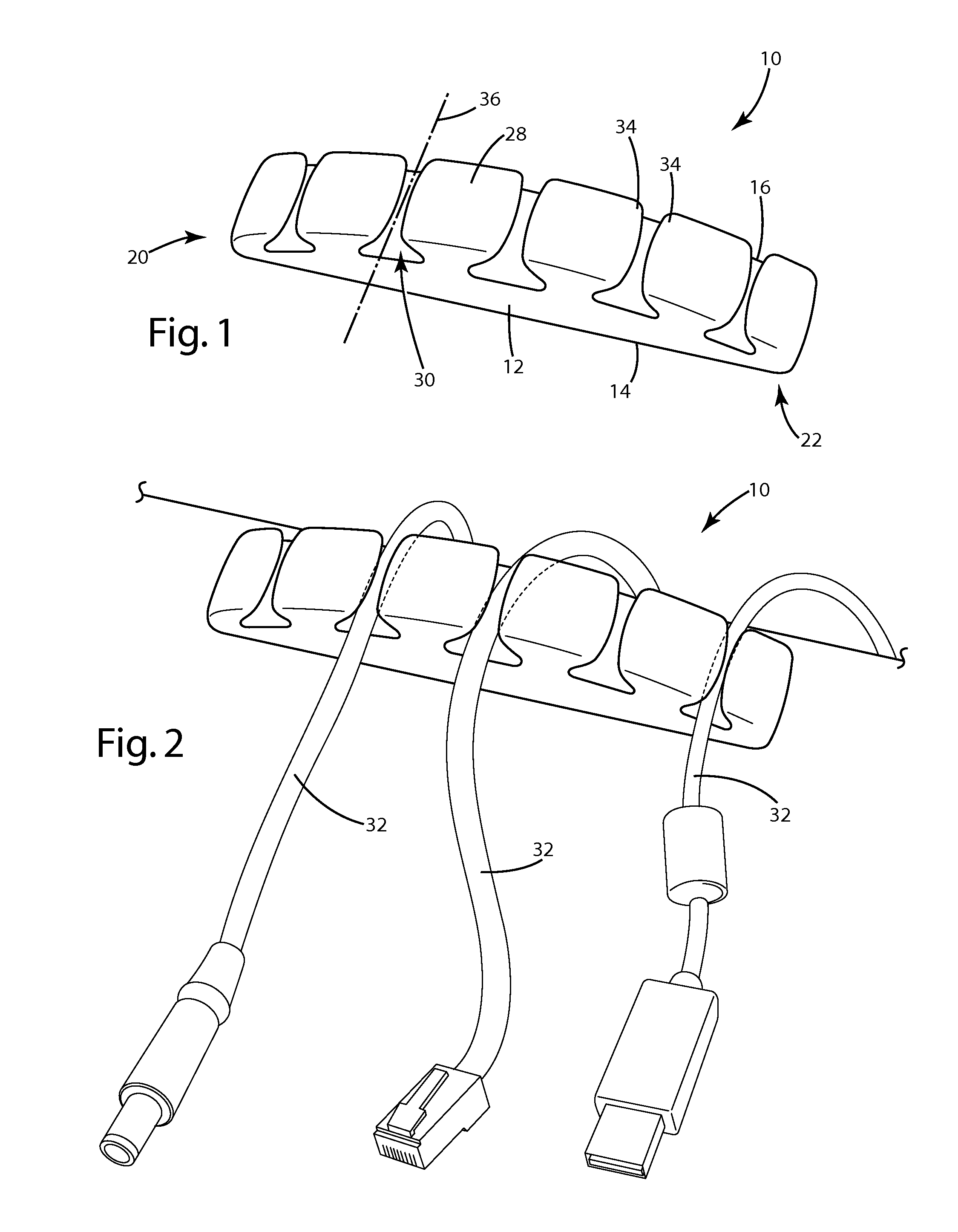
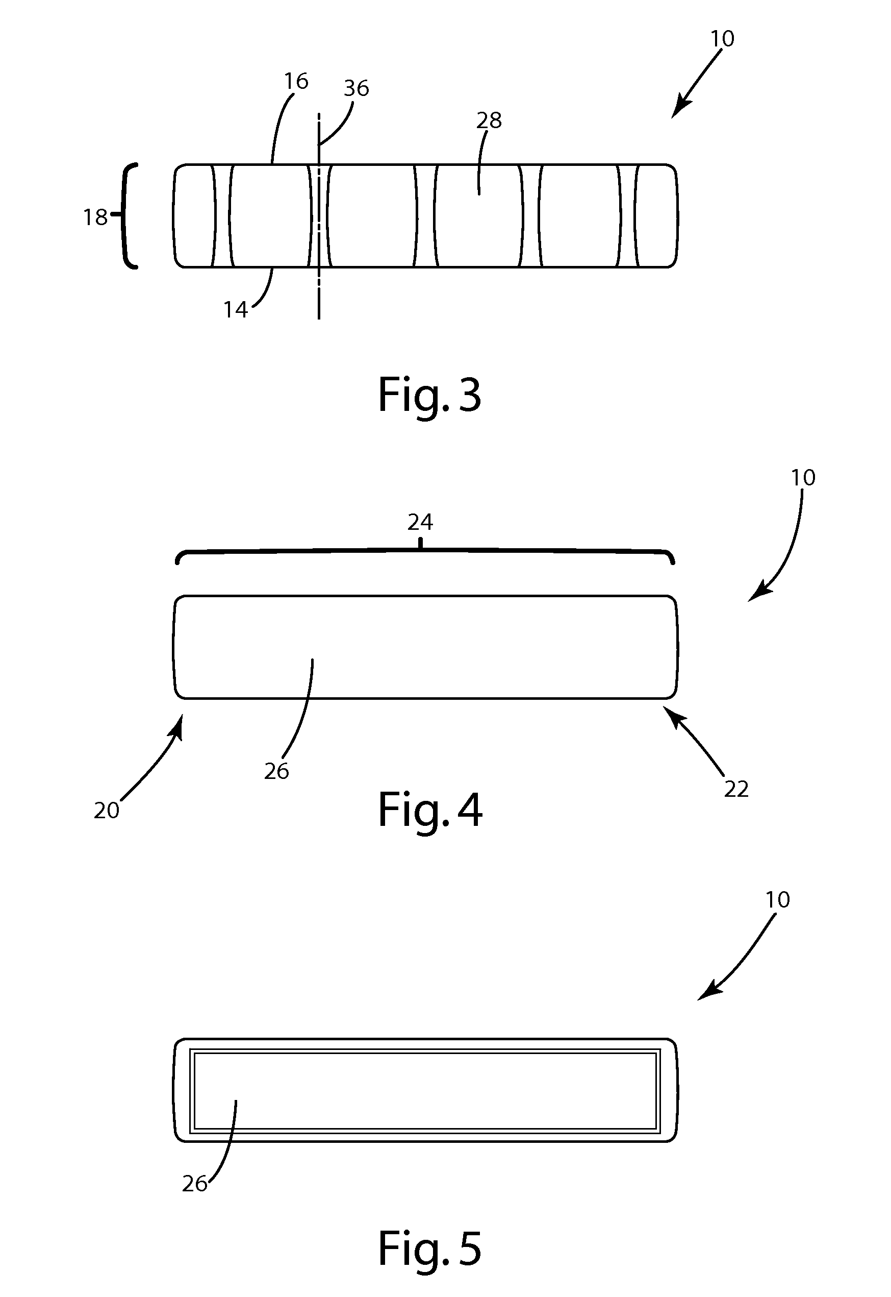
[0023]In yet another preferred embodiment of the present invention, the one or more apertures of the top surface comprise a width that is greater proximate the front and rear sides than a midpoint therebetween. Optionally the top surface may be arcuate. Additionally, in one embodiment, the top surface comprises one or more tabs which are bendable during insertion of a cable into the cable channels.
[0024]The present invention is also directed to a cable organizer, comprising: (a) a front side and a rear side, wherein the front side and the rear side define a width therebetween; (b) a first end and a second end, wherein the first end and the second end define a length therebetween; (c) a bottom surface, wherein the bottom surface is planar and contacts a work surface; (d) a top surface, wherein the top surface includes an aperture for receiving a cable therethrough, wherein the aperture comprises a width that is greater ...
Problems solved by technology
While the above-identified cable organizers exist, their structural configurations remain non-desirous and / or problematic.
Method used
Image
Click on the blue label to locate the original text in one second.
Reading with bidirectional positioning of images and text.
Examples
Embodiment Construction
[0047]While this invention is susceptible of embodiment in many different forms, there is shown in the drawings and will herein be described in detail several specific embodiments with the understanding that the present disclosure is to be considered as an exemplification of the principles of the invention and is not intended to limit the invention to the embodiments illustrated.
[0048]It will be understood that like or analogous elements and / or components, referred to herein, may be identified throughout the drawings with like reference characters.
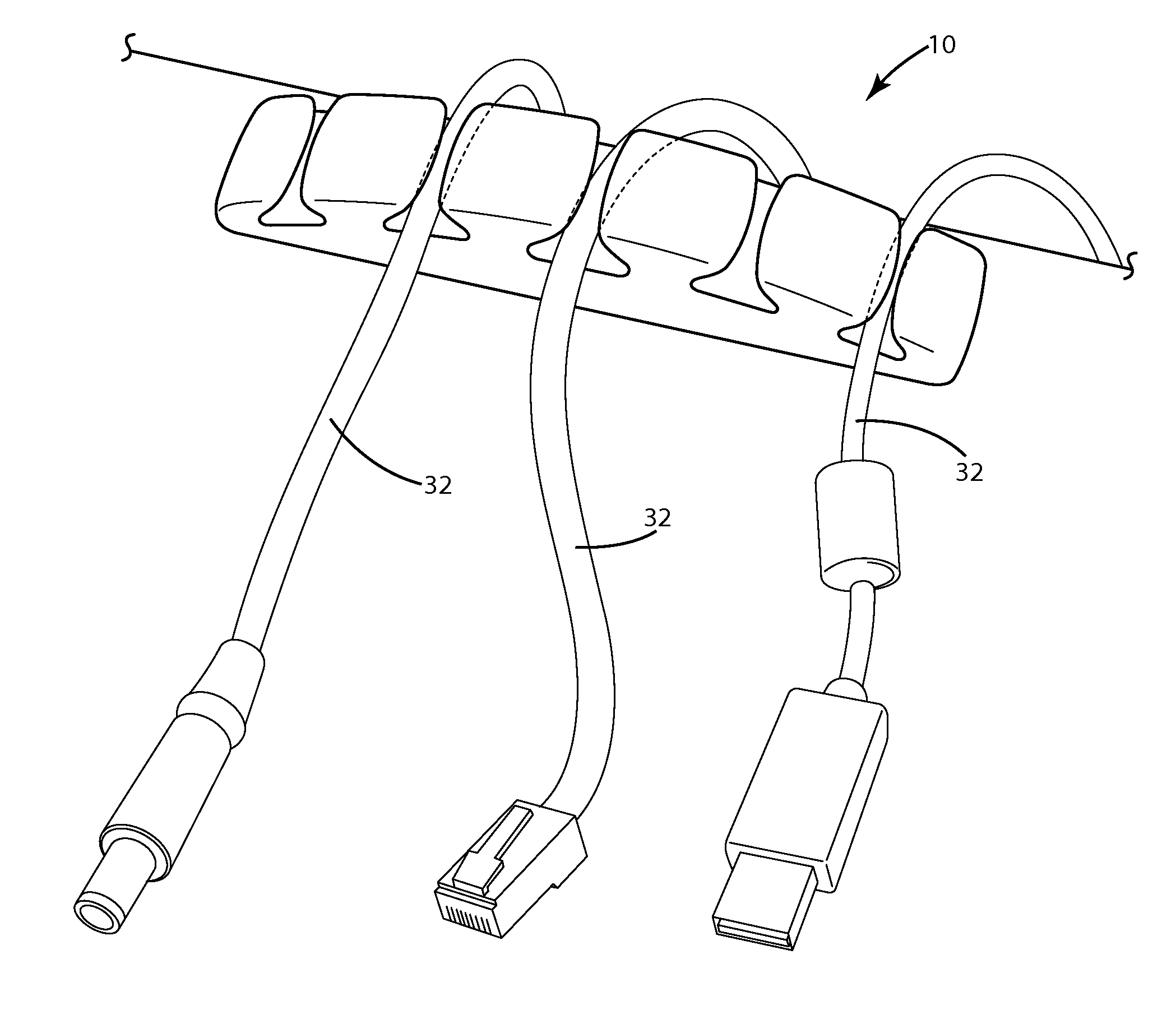
[0049]In accordance with the present invention, the cable organizers disclosed herein, among other things, are configured to facilitate releasable insertion of a cable into one or more cable channels such that the cable is retained in the one or more channels during normal use and removable by a user upon upward displacement of the cable by the user.
[0050]Referring now to the collective drawings (i.e., FIGS. 1-18), and to FIG. 1 in particu...
PUM
Abstract
A cable organizer including a front surface and a rear surface, wherein the front surface and the rear surface define a width therebetween; a first end and a second end, wherein the first end and the second end define a length therebetween; a bottom surface, wherein the bottom surface is adapted for placement proximate a work surface; a top surface, wherein the top surface comprises at least one aperture for receiving a cable therethrough, and wherein the top surface comprises at least one of a tab and detent which is controllably bendable, thereby facilitating releasable insertion of a cable into at least one cable channel such that the cable is retained in the at least one cable channel during normal use and removable by a user upon upward displacement of the cable by the user.
Description
CROSS-REFERENCE TO RELATED APPLICATION(S)[0001]This application claims the benefit of U.S. Provisional Application Ser. No. 61 / 288,584, filed Dec. 21, 2009, entitled “Cable Organizer” which is hereby incorporated herein by reference in its entirety, including all references cited therein. This application relates to U.S. Design application Ser. No. 29 / 348,182, filed Dec. 7, 2009, entitled “Cable Organizer,” U.S. Design application Ser. No. 29 / 348,177, filed Dec. 7, 2009, entitled “Cable Organizer,” U.S. Design application Ser. No. 29 / 348,181, filed Dec. 7, 2009, entitled “Cable Organizer,” U.S. Design application Ser. No. 29 / 349,972, filed May 24, 2010, entitled “Cable Organizer,” U.S. Design application Ser. No. 29 / 349,975, filed May 24, 2010, entitled “Cable Organizer,” and U.S. Design application Ser. No. 29 / 349,973, filed May 24, 2010, entitled “Cable Organizer”—all of which are hereby incorporated herein by reference in their entirety.BACKGROUND OF THE INVENTION[0002]1. Field o...
Claims
Application Information
Patent Timeline
Application Date:The date an application was filed.
Publication Date:The date a patent or application was officially published.
First Publication Date:The earliest publication date of a patent with the same application number.
Issue Date:Publication date of the patent grant document.
PCT Entry Date:The Entry date of PCT National Phase.
Estimated Expiry Date:The statutory expiry date of a patent right according to the Patent Law, and it is the longest term of protection that the patent right can achieve without the termination of the patent right due to other reasons(Term extension factor has been taken into account ).
Invalid Date:Actual expiry date is based on effective date or publication date of legal transaction data of invalid patent.

