Charged particle cancer therapy imaging method and apparatus

a cancer therapy and charge particle technology, applied in the field of solid cancer treatment, can solve the problems of reducing the ability to repair damaged dna, affecting the treatment effect, and affecting the patient's diagnosis,

Active Publication Date: 2011-06-23
BALAKIN ANDREY VLADIMIROVICH +1
View PDF108 Cites 110 Cited by
  • Summary
  • Abstract
  • Description
  • Claims
  • Application Information

AI Technical Summary

Benefits of technology

[0057]The invention comprises a cancer the...

Problems solved by technology

These particles damage the DNA of cells, ultimately causing their death.
Cancerous cells, because of their high ...

Method used


Image

  • Charged particle cancer therapy imaging method and apparatus
  • Charged particle cancer therapy imaging method and apparatus
  • Charged particle cancer therapy imaging method and apparatus

Examples


Embodiment Construction

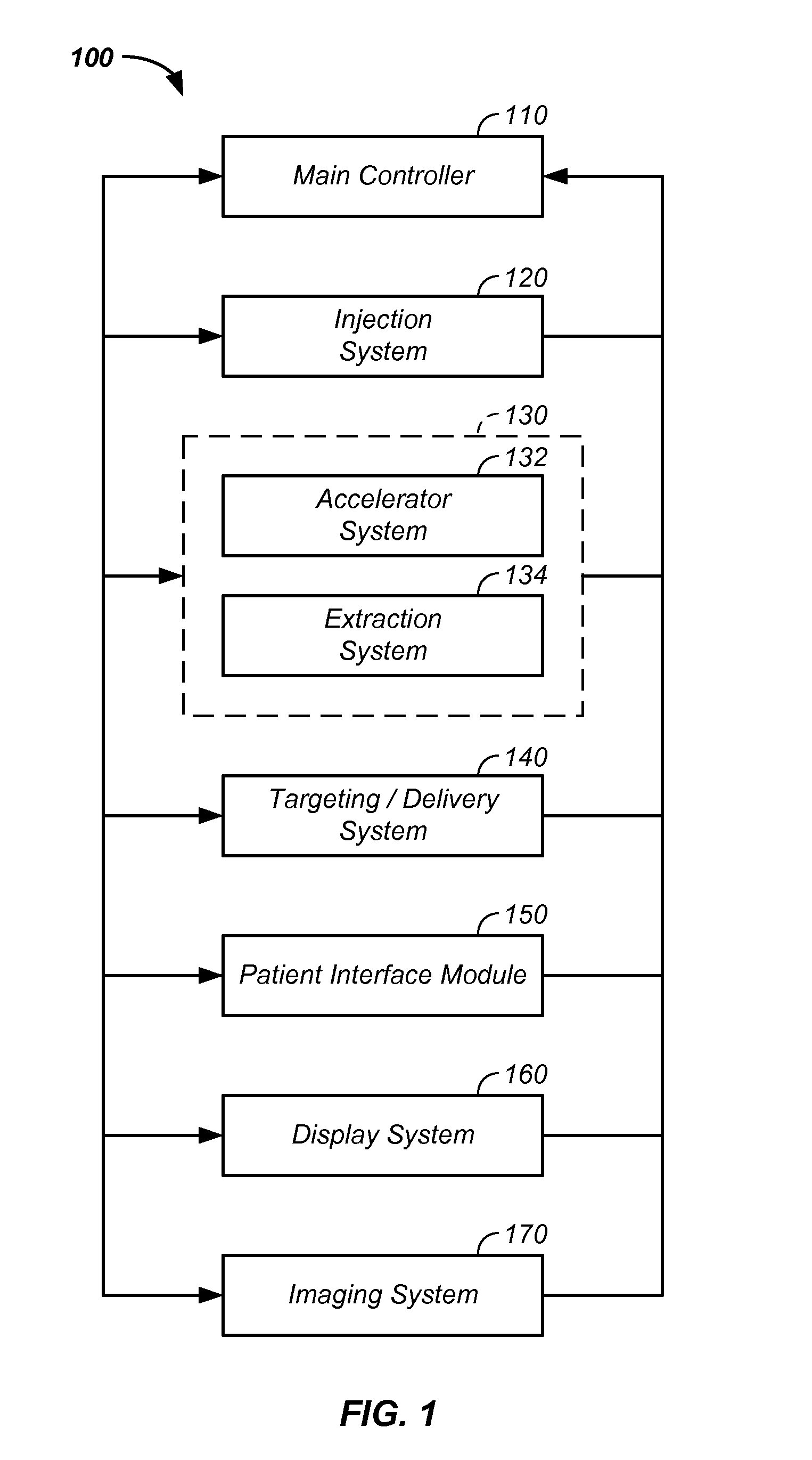
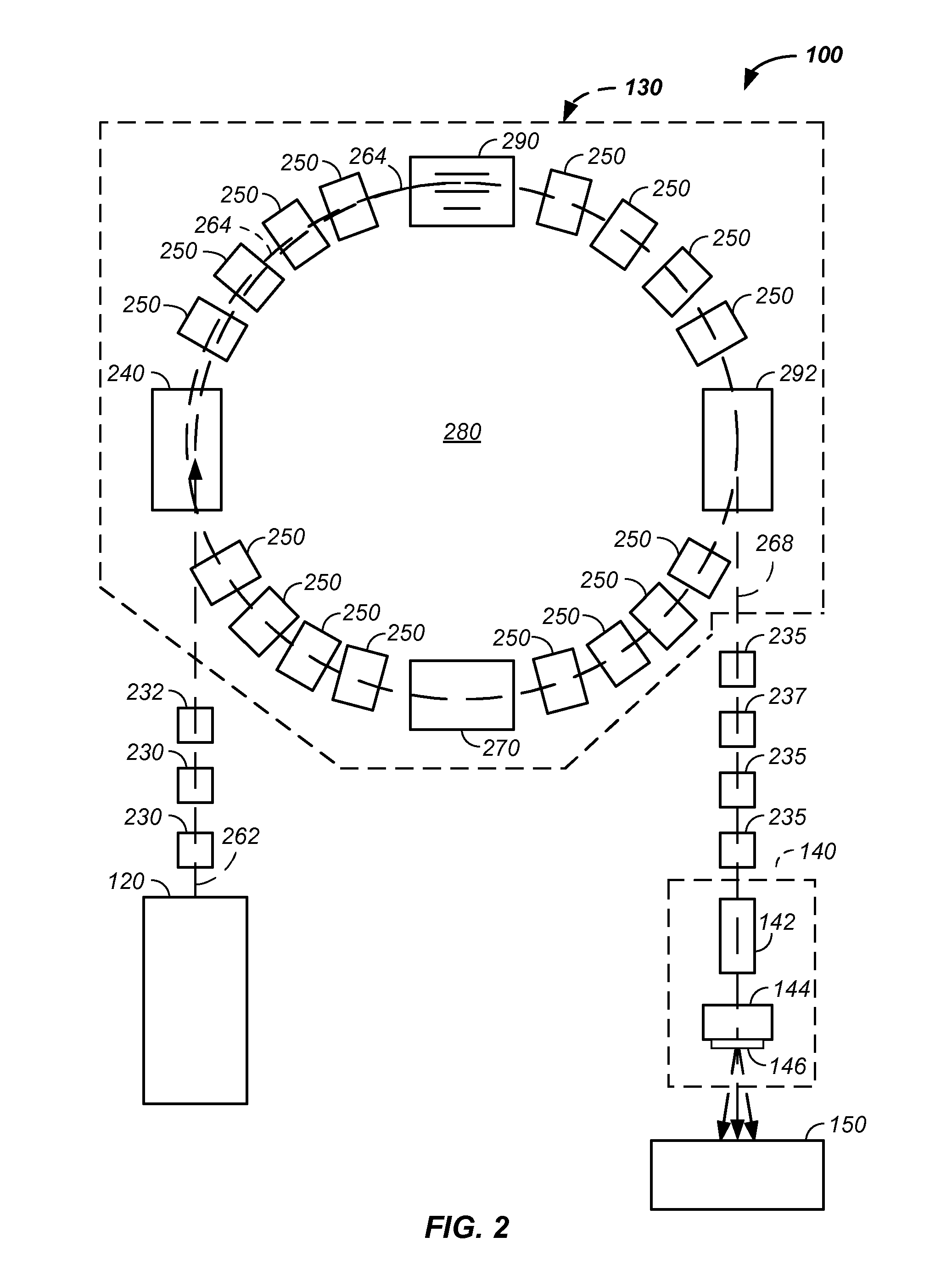
[0105]The invention relates generally to treatment of solid cancers. More particularly, the invention relates to a method and apparatus imaging a charged particle cancer therapy system.

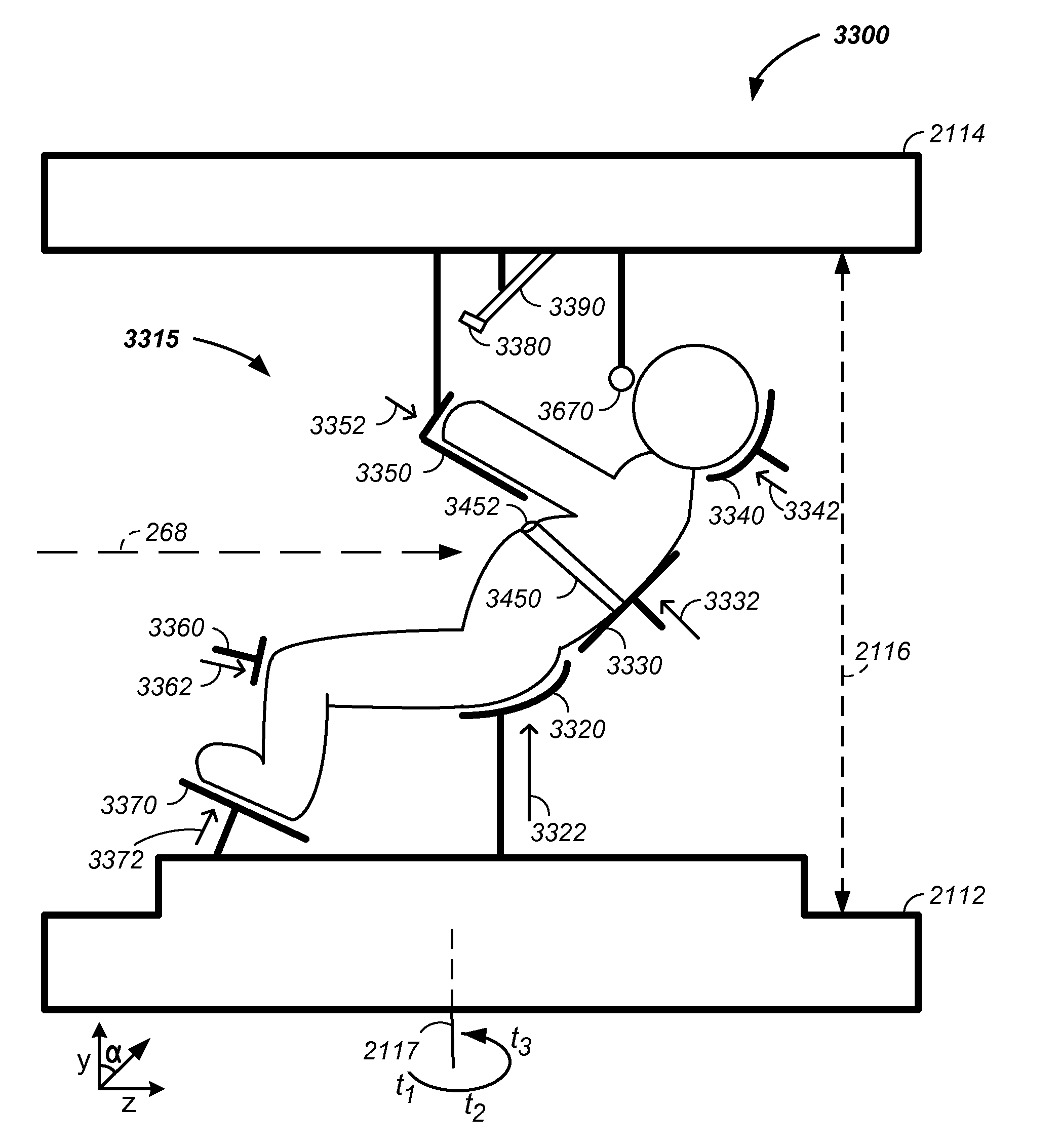
[0106]In one embodiment, safety systems for a charged particle system are implemented. For example, the safety system includes any of: multiple X-ray images from multiple directions, a three-dimensional X-ray image, a proton beam approximating a path of an X-ray beam, tight control of a proton beam cross-sectional area with magnets, ability to control proton beam energy, ability to control proton beam energy, a set of patient movement constrains, a patient controlled charged particle interrupt system, distribution of radiation around a tumor, and timed irradiation in terms of respiration.

[0107]In another embodiment, the tumor is imaged from multiple directions in phase with patient respiration. For example, a plurality of two-dimensional pictures are collected that are all in the about the same phase ...


PUM


Abstract

The invention relates to a method and apparatus for treatment of a solid tumor. More particularly, the invention comprises a multi-axis and/or multi-field charged particle cancer therapy system. In one embodiment, the tumor is imaged from multiple directions in phase with patient respiration. The two-dimensional images are combined to produce a three-dimensional picture of the tumor relative to patient features. The resulting three-dimensional image is used in generation of a radiation treatment plan and subsequent radiation therapy with the radiation beam in terms of control of two-dimensional beam trajectory, delivered beam energy, delivered beam intensity, and/or beam velocity each as a function of patient vertical translation position, patient rotation position, and/or patient respiration.

Description

CROSS-REFERENCES TO RELATED APPLICATIONS[0001]This application:[0002]is a continuation-in-part of U.S. patent application Ser. No. 12 / 425,683 filed Apr. 17, 2009, which claims the benefit of:[0003]U.S. provisional patent application No. 61 / 055,395 filed May 22, 2008;[0004]U.S. provisional patent application No. 61 / 137,574 filed Aug. 1, 2008;[0005]U.S. provisional patent application No. 61 / 192,245 filed Sep. 17, 2008;[0006]U.S. provisional patent application No. 61 / 055,409 filed May 22, 2008;[0007]U.S. provisional patent application No. 61 / 203,308 filed Dec. 22, 2008;[0008]U.S. provisional patent application No. 61 / 188,407 filed Aug. 11, 2008;[0009]U.S. provisional patent application No. 61 / 188,406 filed Aug. 11, 2008;[0010]U.S. provisional patent application No. 61 / 189,815 filed Aug. 25, 2008;[0011]U.S. provisional patent application No. 61 / 201,731 filed Dec. 15, 2008;[0012]U.S. provisional patent application No. 61 / 205,362 filed Jan. 12, 2009;[0013]U.S. provisional patent applicati...

Claims


Application Information

Patent Timeline
IPC IPC(8): H01J3/14A61B6/04A61B6/03A61N5/10
CPCA61N5/10A61N2005/1087A61N5/1064H05H13/04A61N5/1049H05H7/10
Inventor BALAKIN, VLADIMIR
Owner BALAKIN ANDREY VLADIMIROVICH
Why Eureka
Try Eureka