Cellular, electron cooled storage ring system and method for fusion power generation

a fusion power and electron cooled technology, applied in nuclear reactors, greenhouse gas reduction, nuclear engineering, etc., can solve the problems of device not producing useful energy and loss of beam particles, and achieve the effect of large output fusion energy

Inactive Publication Date: 2011-06-30
LARSON DELBERT JOHN
View PDF4 Cites 28 Cited by
  • Summary
  • Abstract
  • Description
  • Claims
  • Application Information

AI Technical Summary

Benefits of technology

[0023]The present invention, which addresses the above desires and provides various advantages, resides in a method and system for generating large levels of output fusion energy. The system includes particle supplies for generating beams of projectile particles, overlapping storage rings for containing and recycling the projectile particles, electron cooling systems for stabilizing and restoring energy to the projectile particles, and interaction regions where the storage rings overlap for initiating nuclear fusion reactions with the projectile particles to generate the desired energy source. The system also includes a plurality of dipoles, quadrupoles, torroids and solenoids selectively situated around the rings to “bend” the direction of travel of the projectile particles within the system as well as to focus the beams down to a small size when they come into collision.

Problems solved by technology

Without the electron cooling systems, the particle beams would develop internal trajectories that would cause such a significant loss of beam particles that the device would not produce useful energy.

Method used


Image

  • Cellular, electron cooled storage ring system and method for fusion power generation
  • Cellular, electron cooled storage ring system and method for fusion power generation
  • Cellular, electron cooled storage ring system and method for fusion power generation

Examples


Embodiment Construction

Summary Description of Preferred Embodiment Operation

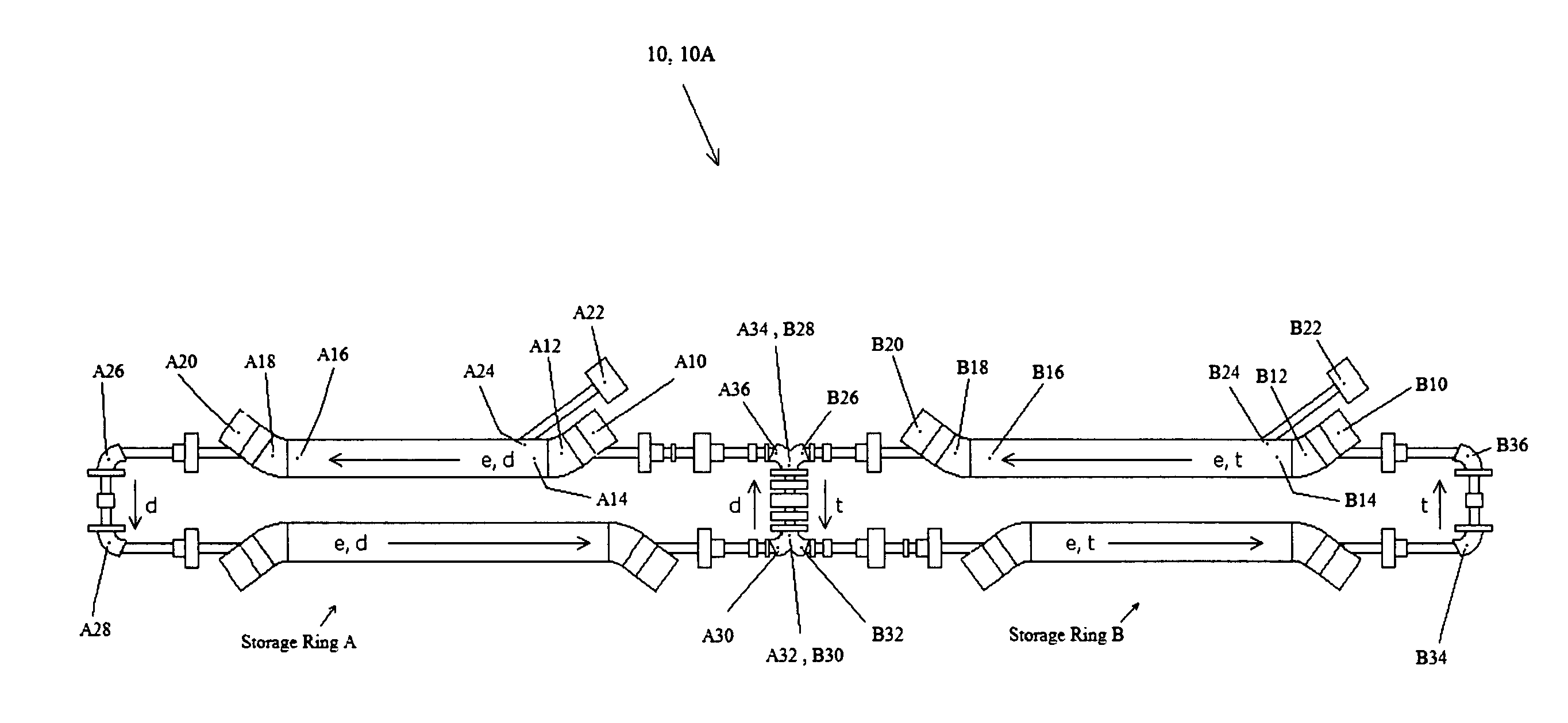
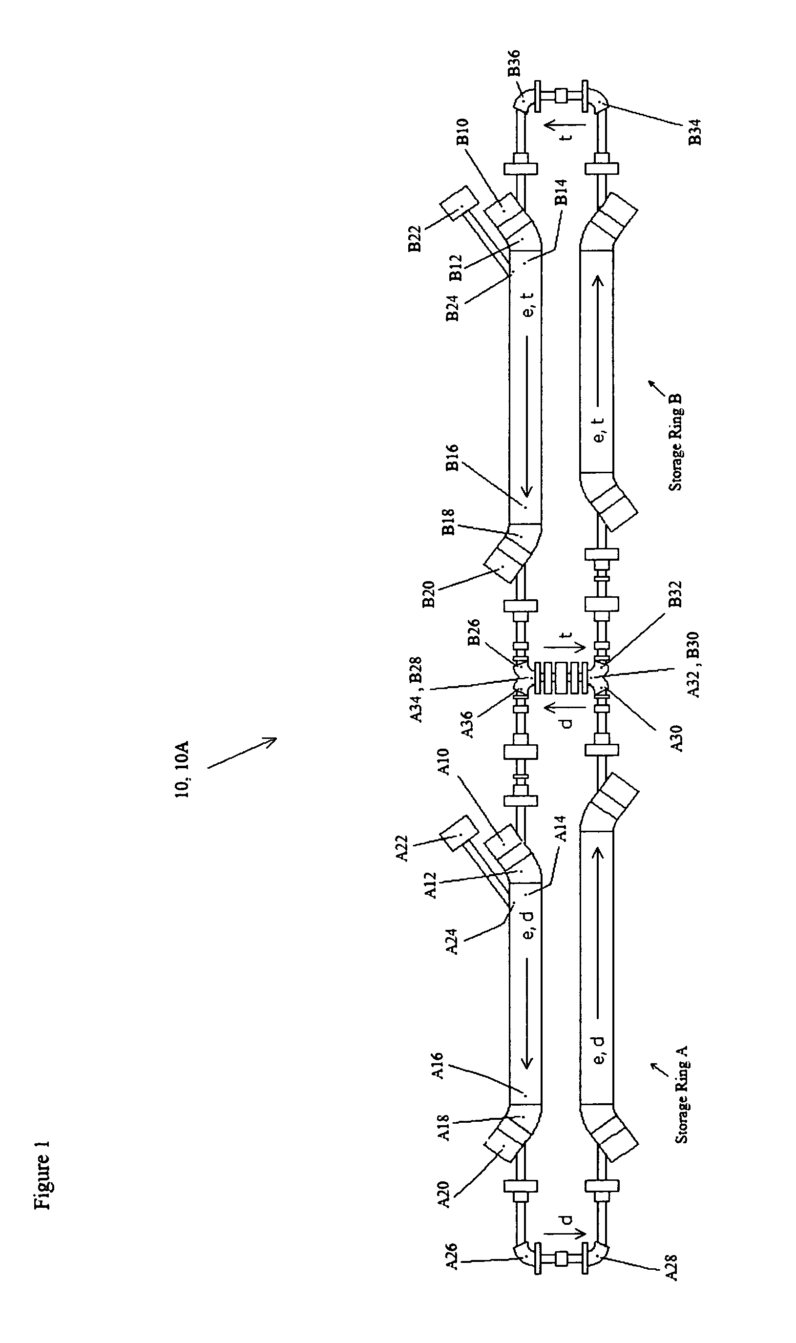
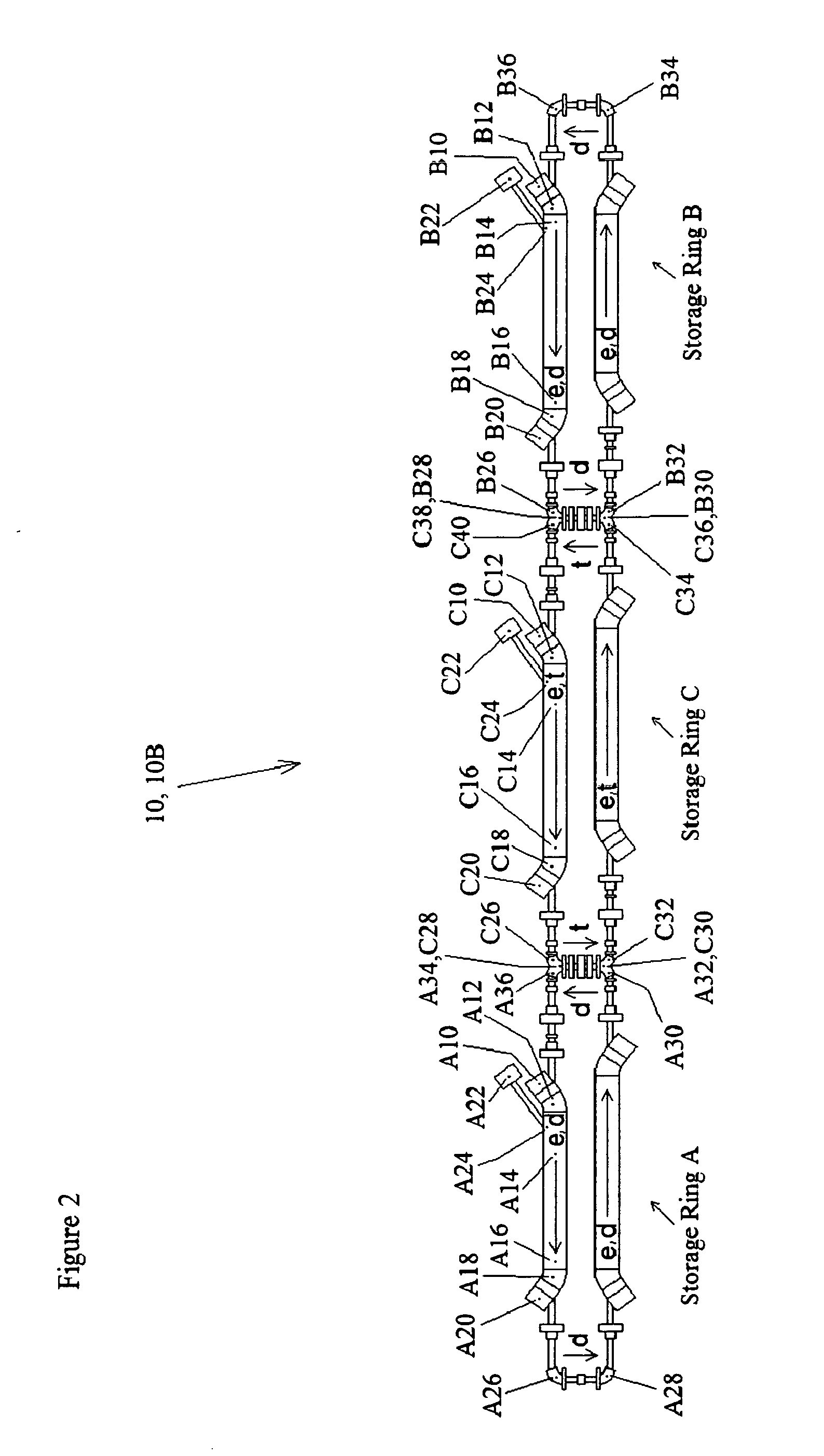
[0042]An electron-cooled intersecting storage ring system 10A employing two intersecting storage rings for achieving large amounts of fusion reactions is shown in FIG. 1. An electron-cooled intersecting storage ring system 10B employing three intersecting storage rings for achieving large amounts of fusion reactions is shown in FIG. 2. Preferred embodiments can contain four, five, or more intersecting storage rings. This description of the preferred embodiments will use deuterium and tritium as the example ions, but, as mentioned in the claims, other ions could be used in the invention as well.

[0043]The electron-cooled intersecting storage ring system 10 utilizes a combination of elements, including an ion source 20 for supplying ions 22, an electron source 24 for supplying electrons 26, a vacuum chamber 28 for containing particles within a region of low pressure, solenoidal wire windings 30 and torroidal wire windings 32 to provi...


PUM


Abstract

A cellular electron cooled storage ring system and method for achieving particle-fusion based energy, including a vacuum chamber to allow electron beam and ion beam merging and separation, cathodes to generate the electron beams, collectors to collect the electron beams, and magnetic field generation devices to guide the electrons and ions on their desired trajectories as well as contain neutralizing particles. By overlapping the electron and ion beams, thermal energy is transferred from the ion beams to the electron beams, which allows the invention to overcome particle losses due to resonances, scattering and heating of the ion beams. Advantageously, ions are accelerated to an energy that is near optimum for fusion reactions to occur, and uses electron energies that maintain this advantageous situation. Advantageously, the recirculation of ions that do not fuse or scatter at too large of an angle is allowed, giving such ions additional chances to participate in a desired fusion reaction. Advantageously, the invention allows for a continual addition of new ions to be added to the circulating ions already in the system. This combination of advantages results in a significant improvement in the predicted output power to input power ratio over previous particle fusion technologies. The invention will also enable improved yields of fast neutrons for materials testing.

Description

REFERENCES CITEDReferenced byU.S. Patent Documents[0001]U.S. Pat. No. 5,854,531 December 1998 Young, et al.[0002]U.S. Pat. No. 5,152,955 October 1992 Russell[0003]U.S. Pat. No. 5,138,271 August 1992 Ikegami[0004]U.S. Pat. No. 5,001,438 March 1991 Miyata, et al.[0005]U.S. Pat. No. 4,867,939 Sep. 19, 1989 DeutchOther Documents[0006]G. I. Budker, The 1966 Proc. Int. Symp. Electron and Positron Storage Rings, Saclay. Atomnaya Energiya vol. 22 p. 346, 1967.[0007]L. Spitzer, “Physics of Fully Ionized Gases”, (New York: Interscience, 1956) pp. 80-81.[0008]G. I. Budker, et al., Particle Accelerators, Vol. 7, 197-211 (1976).[0009]M. Bell, et al., Physics Letters, Vol. 87B, No. 3, (1979).[0010]T. Ellison, et al., IEEE Trans. Nuc. Sci., Vol. NS-30, No. 4, 2636-2638, (1983).[0011]D. J. Larson, et al., “Operation of a prototype intermediate-energy electron cooler”, NIM, A311, 30-33 (1992).[0012]F. Krienen, “Electron Cooling”, Chapter 2 in “Handbook of Accelerator Physics and Engineering”, Eds. W...

Claims


Application Information

Patent Timeline
Patent Type & Authority Applications(United States)
IPC IPC(8): G21B1/00
CPCG21B1/00G21B1/15G21B3/006Y02E30/16H05H7/06Y02E30/10
Inventor LARSON, DELBERT JOHN
Owner LARSON DELBERT JOHN
Why Eureka
Try Eureka