Protective member for automatic open close umbrella with Anti-springing effect

a protection member and umbrella technology, applied in the direction of umbrellas, traveling accessories, apparel, etc., can solve the problems of easy wear of the tip of the umbrella, achieve the effects of not easily worn out, movement, connection, movement and movement among the ratch

a protection member and umbrella technology, applied in the direction of umbrellas, traveling accessories, apparel, etc., can solve the problems of easy wear of the tip of the umbrella, achieve the effects of not easily worn out, movement, connection, movement and movement among the ratch

US20110232707A1Active Publication Date: 2011-09-29WU TSUN ZONG

Image

  • Protective member for automatic open close umbrella with Anti-springing effect
  • Protective member for automatic open close umbrella with Anti-springing effect
  • Protective member for automatic open close umbrella with Anti-springing effect

Examples


Embodiment Construction

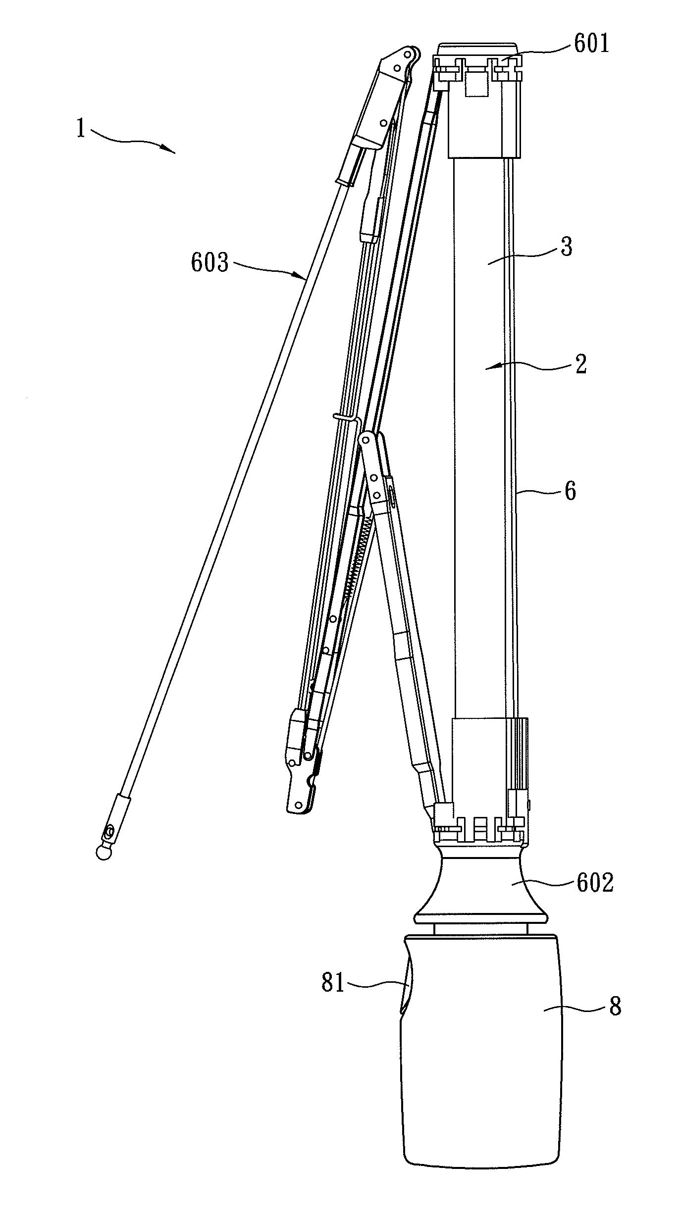
[0030]A protective device for automatic open close umbrellas is applied to a folding umbrella such as three folding umbrella but not limited to. In this embodiment, a three folding umbrella is used as an example. In figures, only a left side of an umbrella frame is displayed while the right side thereof is omitted because the umbrella frame has symmetrical structure.

[0031]Refer from FIG. 6 to FIG. 11, an automatic open close umbrella 1 generally includes an umbrella shaft 2 formed by an outer tube 3, a middle tube and an inner tube sleeved with one another, an upper runner 601 fixed on the top of the umbrella shaft 2, a lower runner 602 sliding and arranged around the umbrella shaft 2, and an umbrella frame 603. The upper runner 601, the lower runner 602 and the umbrella frame 603 form a connecting structure. An upper pulley base 4 is disposed on the top of the outer tube 3 while a core tube 5 mounted in the outer tube 3 and connected with the bottom of the upper pulley base 4 moves...


PUM


Abstract

A protective device for automatic open close umbrellas is revealed. The protective device includes a ratchet mounted in a handle and rotating elastically for retracting or releasing a string, a string whose bottom end is fixed on the ratchet while a top end is fixed on an outer tube of an umbrella shaft or a core tube, and a locking member that is reverse L-shaped and is arranged with an elastic member for turning back therein. The locking member includes an upper part, a lower part, and a middle axle, used as a first-class lever. The upper part is against the bottom of the umbrella shaft so that the fastener can lean against a top surface of the upper part. When the umbrella shaft is gradually folded, the top surface of the upper part of the locking member is separated from the fastener while the bottom of the lower part is locked to one of the ratchet teeth of the ratchet elastically so as to achieve anti-springing effect.

Description

BACKGROUND OF THE INVENTION[0001]The present invention relates to a protective member for automatic open close umbrellas, especially to a protective member for automatic open close umbrellas with anti-springing effect that prevents an umbrella shaft from springing back effectively when a force applied to the umbrella shaft disappears suddenly.[0002]The automatic open close umbrella available now opens and closes umbrella frames by pressing a button on a handle. While closing the umbrella, users need to slide down an umbrella shaft toward the handle so as to shorten the umbrella shaft to a locating point for being locked. That's the closed state. While during closing process of the umbrella shaft, the force applied to the umbrella shaft may suddenly disappear due to improper operations and the umbrella shaft is stretched out and users may get hurt. The followings are prior arts of protective members for automatic open close umbrellas.[0003]Refer to FIG. 1, a protective member for aut...

Claims


Application Information

Patent Timeline
29 Sep 2011
Publication
US20110232707A1
IPC
A45B25/16
CPC
A45B19/04; A45B25/143; A45B19/10
Inventors
WU, TSUN-ZONG; CHEN, HSIEN-JUNG