Off-centred pusher device for steering an automobile

a pusher device and automobile technology, applied in the direction of steering gears, steering parts, portable lifting, etc., can solve the problems of loss of contact between the spring and the rack, variation in the orientation and intensity of the force applied to the rack, and strong degradation of the function performed by the off-centred pusher device. , to achieve the effect of compactness and saving

Inactive Publication Date: 2011-11-03
JTEKT EURO
View PDF15 Cites 3 Cited by
  • Summary
  • Abstract
  • Description
  • Claims
  • Application Information

AI Technical Summary

Benefits of technology

[0009]The present invention sets out to remedy these drawbacks, hence to improve the functioning of an off-centred pusher device for rack-and-pinion steering, through better control over the movements and positions of the members of the pusher device.
[0011]Therefore, the principle of the invention is to separate the function compensating for play due to assembly and wear, which is ensured by the eccentric support itself, from the function of absorbing straightness defects of the rack and optionally of the pinion, which is ensured by the translational movement of the casing subjected to the action of damping spring means which themselves bear upon the housing. This separation of the two functions particularly provides for good guidance of the rack resting directly on a rigid support with an eccentric part. It also limits the causes of degraded irreversibility of the pusher device by stabilising the bearing points of the rotary support.
[0014]Advantageously, the rotary support with eccentric inner periphery does not completely surround the rack but has an arched <<wedge-like>> shape. Therefore the entire mechanism remains compact and it can be positioned on the side of the back of the rack directed away from the side of the steering pinion. In addition to the advantages of compactness and savings with said arrangement, it allows the assembly of two bellows seals and two end-of-travel abutments that are identical at each end of the steering housing, whilst not forming any obstacle between the steering pinion and the end-of-travel abutment of the rack.

Problems solved by technology

However, in the arrangement according to patent U.S. Pat. No. 6247375 B1, the fact that the plate spring is placed between the rotatable yoke and the rack means that when the rack is subjected to variable forces it does not always bear in similar manner upon the spring, which may cause losses of contact between the said spring and the rack.
In addition, the plate spring changes position over time having regard to the progressive rotation of the yoke, which causes variation in the orientation and intensity of the forces applied to the rack.
This may all lead to strong degradation of the function performed by the off-centred pusher device.

Method used


Image

  • Off-centred pusher device for steering an automobile
  • Off-centred pusher device for steering an automobile
  • Off-centred pusher device for steering an automobile

Examples


Embodiment Construction

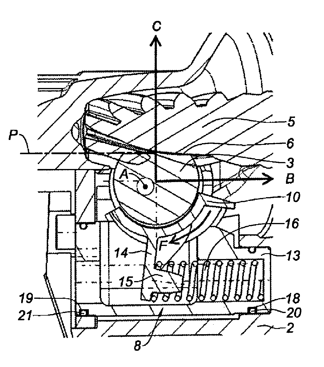
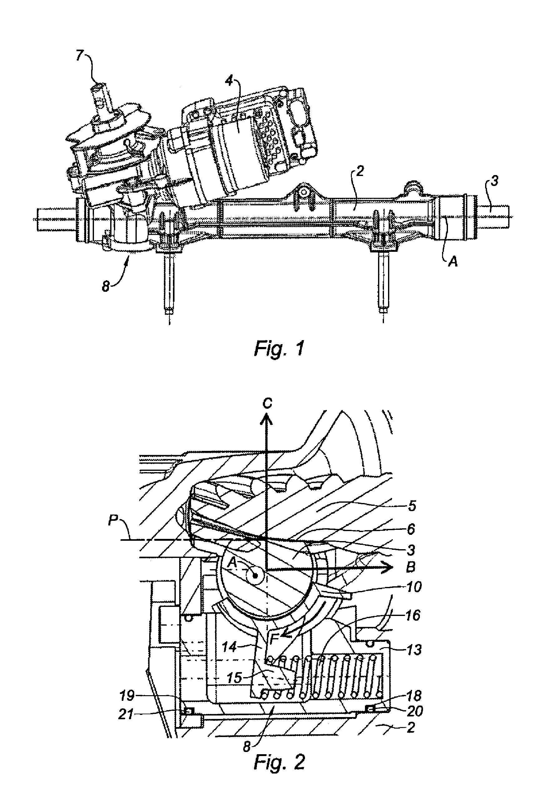
[0020]FIG. 1 partly shows a steering system for motor vehicle with its steering housing 2 that extends along a longitudinal axis A, which is also the longitudinal axis of the rack 3 slidingly mounted in the housing 2. In the illustrated example, the steering is electric power steering with an electric motor 4 which is coupled with a steering pinion 5 (see also FIG. 2) meshing with the teeth 6 of the rack 3, the plane of these teeth 6 being indicated by P. The input shaft is referenced 7 to which the steering column (not illustrated) is coupled and operated by means of the steering wheel of the vehicle.

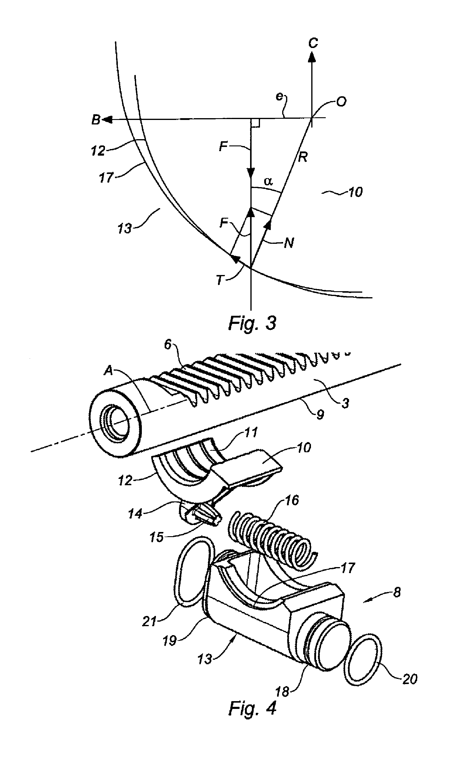
[0021]A pusher device generally designated under the reference number 8 is provided in the vicinity of the steering pinion 5 to press the teeth 6 of the rack 3 against the pinion 5, the pusher device 8 being shown in detail in FIGS. 2 and 4.

[0022]The pusher device 8 is positioned on the back side 9 of the rack 3, in other words on the side directed away from the teeth 6 of this rack 3 ...


PUM


Abstract

The invention relates to a pusher device (8) that includes a rotary bearing (10) having an inner periphery (11) that is off-centre relative to the outer periphery (12). In order to compensate for wear, the bearing (10) is rotationally urged in one direction (F) by a spring (10) and is thus pressed against the back (9) of a rack (3) that is then pushed back against the teeth of the steering sprocket (5). The rotary bearing (10) is rotatingly mounted in a housing (13) that is in turn mounted on a steering casing (2) so as to be capable of sliding in a direction (B) parallel to a plane (P) of the teeth (6) of the rack (3) and orthogonal to the axis (A) of said rack. Shock-absorbing spring means (20, 21) are arranged between the sliding housing (13) and the steering casing (2) for absorbing the straightness defects of the rack (3).

Description

TECHNICAL FIELD[0001]The present invention generally concerns rack-and-pinion steering systems for motor vehicles. More particularly this invention relates to a pusher device for motor vehicle steering systems. Further particularly it relates to a so-called off-centred pusher device.BACKGROUND[0002]In most steering systems which currently equip motor vehicles a steering pinion is linked in rotation with a steering column which is operated by means of a steering wheel of the vehicle, often with hydraulic or electric powering. The steering pinion meshes with a rack mounted so that it slides in longitudinal direction inside a steering housing. The two ends of the rack, outside the housing, are respectively coupled with two tie rods which themselves are respectively associated with left and right steerable wheels of the vehicle. Therefore the rotation of the steering wheel in one or other direction transmitted by the steering column to the pinion is converted into corresponding translat...

Claims


Application Information

Patent Timeline
Patent Type & Authority Applications(United States)
IPC IPC(8): F16H55/28
CPCB62D3/123Y10T74/19623Y10T74/1967F16H55/283
Inventor PLATARET, NICOLASBROCHOT, PATRICE
Owner JTEKT EURO
Why Eureka
Try Eureka