Stylus

Inactive Publication Date: 2011-12-01
SHENZHEN FUTAIHONG PRECISION IND CO LTD +1
View PDF7 Cites 1 Cited by
  • Summary
  • Abstract
  • Description
  • Claims
  • Application Information

AI Technical Summary

Problems solved by technology

However, typical styluses have no other functions like a pen for writing on a paper.

Method used


Image

  • Stylus
  • Stylus
  • Stylus

Examples


Embodiment Construction

[0014]In this exemplary embodiment, the stylus is used to contact a touch screen display of an electronic device such as a mobile telephone. The mobile telephone described herein is a representation of the type of wireless communication device that may benefit from the exemplary embodiment. However, it is to be understood that the exemplary embodiment may be applied to any type of hand-held or portable device including, but not limited to, the following devices: radiotelephones, cordless phones, paging devices, personal digital assistants, portable computers, pen-based or keyboard-based handheld devices, remote control units, portable media players (such as an MP3 or DVD player) that have wireless communication capability. Accordingly, any reference herein to the mobile telephone should also be considered to apply equally to other portable wireless electronic devices.

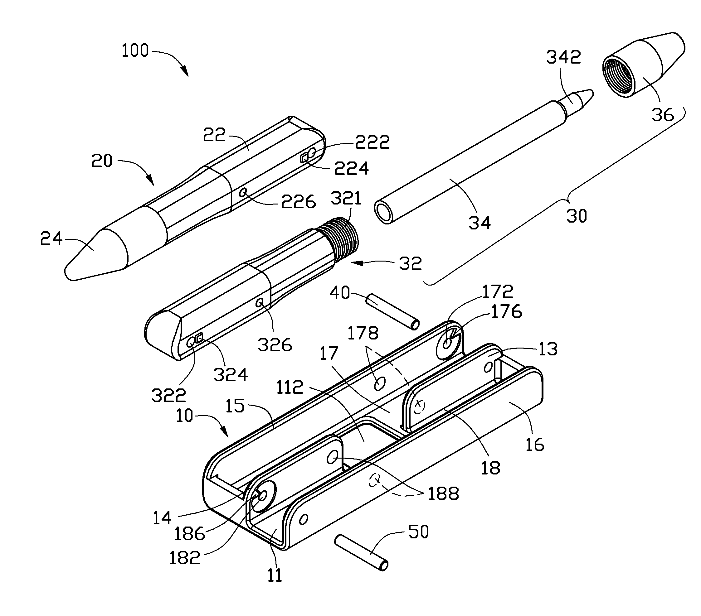
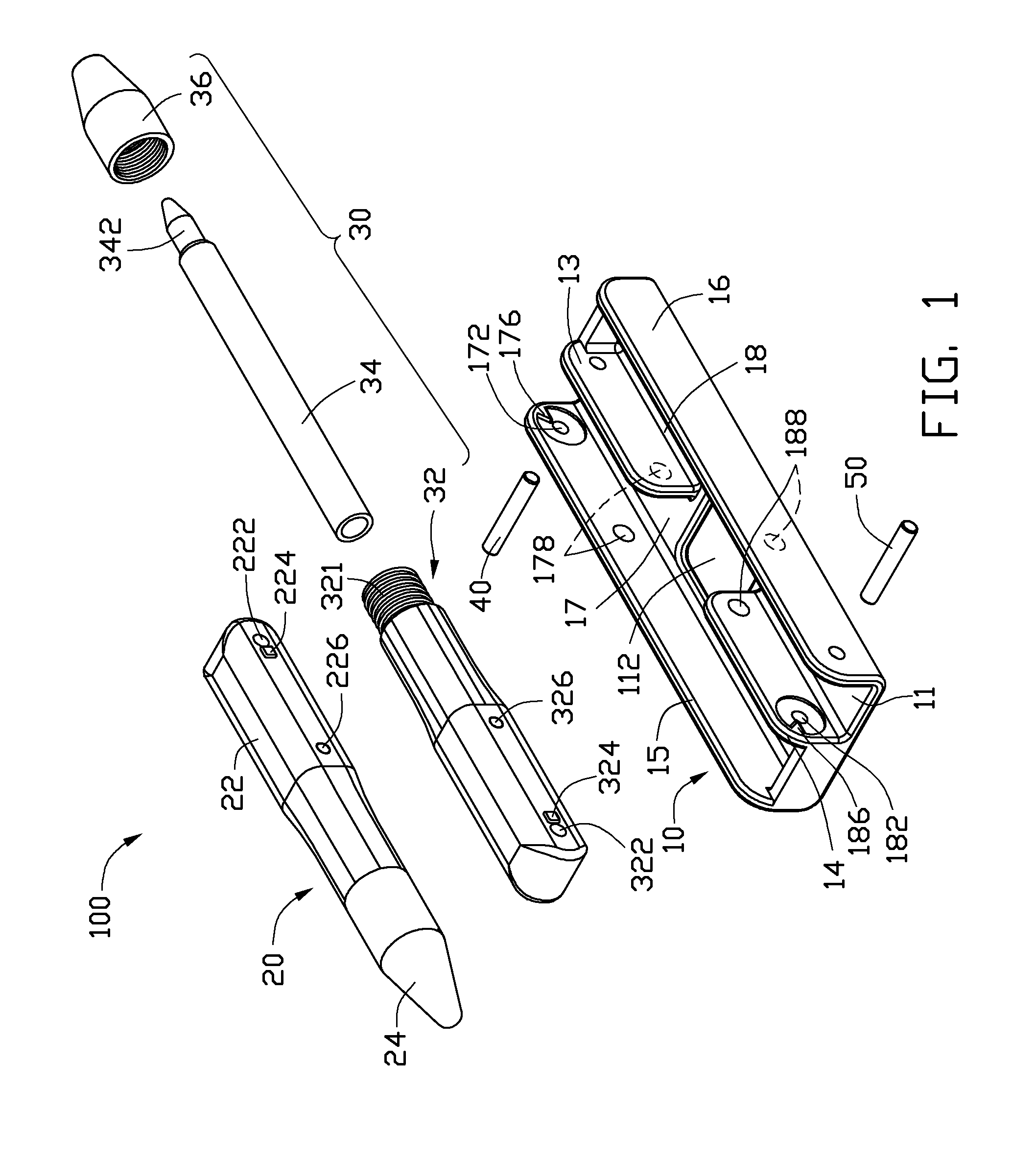
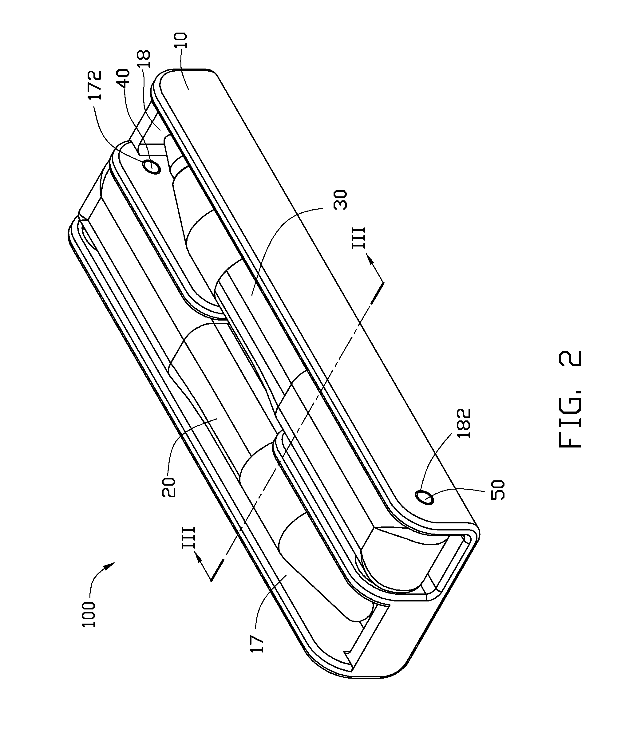
[0015]Referring to FIGS. 1 and 2, a stylus 100 includes a housing 10, a stylus body 20 and a pen 30. The stylus body ...


PUM


Abstract

A stylus includes a housing, a stylus body including a tip, a pen including a head, a first rotating member and a second rotating member. The first rotating member is coupled between the housing and the stylus body so the stylus body rotatably engages with the housing. The second rotating member is coupled between the housing and the pen so the pen rotatably engages with the housing. When the stylus body rotates relative to the housing, the tip moves from a first side of the first rotating member to a second side of the first rotating member opposite to the first side of the first rotating member; when the pen rotates relative to the housing, the head moves from a first side of the second rotating member to a second side of the second rotating member opposite to the first side of the second rotating member.

Description

CROSS-REFERENCE TO RELATED APPLICATIONS[0001]The present application is related to co-pending U.S. patent application Ser. No. (Attorney Docket No. US34009), entitled “STYLUS”, by Liang et al. This application has the same assignee as the present application and has been concurrently filed herewith. The above-identified applications are incorporated herein by reference.BACKGROUND[0002]1. Technical Field[0003]This exemplary disclosure generally relates to retractable / extendable styluses.[0004]2. Description of Related Art[0005]It is well-known that a variety of devices include a touch screen. Examples of such devices include smart phones, personal digital assistants (PDA), pagers, and personal organizers. These devices typically include a display module under the touch screen. The display module generates target images associated with menu options, programs, user choices, and other operations. The user controls the device by pressing the touch screen over the target image with a styl...

Claims


Application Information

Patent Timeline
IPC IPC(8): G06F3/033
CPCB43K23/06B43K24/10G06F3/03545B43K29/18B43K27/02
Inventor LIANG, SHI-XULIU, CHUAN-I
Owner SHENZHEN FUTAIHONG PRECISION IND CO LTD
Why Eureka
Try Eureka