Severable film package for stacked product pieces
Inactive Publication Date: 2011-12-08
INTERCONTINENTAL GREAT BRANDS
27 Cites 10 Cited by
AI-Extracted Technical Summary
Problems solved by technology
One disadvantage is that the foil forming the outer wrap is relatively expensive.
Moreover, foil lacks the marketing and advertising potential of...
Method used
[0023]The embodiments of the present invention relate generally to a packaging device for a plurality of consumable product pieces that are arranged and packed in a longitudinally adjacent direction to one another. The packaging device of the present invention allows for the consumable product pieces to be stored and dispensed from their longitudinally adjacent configuration, The packaging device of the present invention also allows a user to remove one or more consumable product pieces from the package in an effective and efficient manner.
[0024]As shown in FIGS. 1 and 2, the packaging device 10 includes an elongate package 12. The elongate package 12 encloses a plurality of adjacent consumable product pieces 18 in a longitudinal array. As additionally shown in FIGS. 3 and 4, the elongate package 12 may be configured from a sheet 14 or substrate which may be used to cover the plurality of pieces 18 in order to promote support and retention of the consumable product pieces therein. The elongate package 12 may be made various types of plastic, as may be desired. The elongate package 12 may be composed of a sheet 14 of plastic or film wrap. While a sheet or film formed of resilient plastic is shown and contemplated herewith, the present invention contemplates employing a sheet of film formed of any material which is generally not readily rupturable, i.e., rupture-resistant, and rendering it rupturable as described hereinbelow. Other materials that may be employed include polyester (PET), metalized polyester (MPET), polyprolylene (OPP), Metalized polypropylene (MOPP), polyethylenes (PE's, including for example LDPE, MDPE, and HDPE), or polyethylene co-polymers (including LUPE, EVA, and surlyn ionomer). Desirable characteristics of the sheet 14 used with the present invention include, for e...
Abstract
A packaging device for supporting and dispensing product includes an elongate package having a wall of a single sheet The elongate package encloses a plurality of adjacent product pieces in a longitudinally stacked array The package has a weakened location extending along the length of the package permitting manual serving of the package therealong to open the package to dispense the product pieces.
Application Domain
CapsClosure caps +2
Technology Topic
EngineeringMechanical engineering
Image
Examples
- Experimental program(1)
Example
DETAILED DESCRIPTION OF THE DRAWINGS
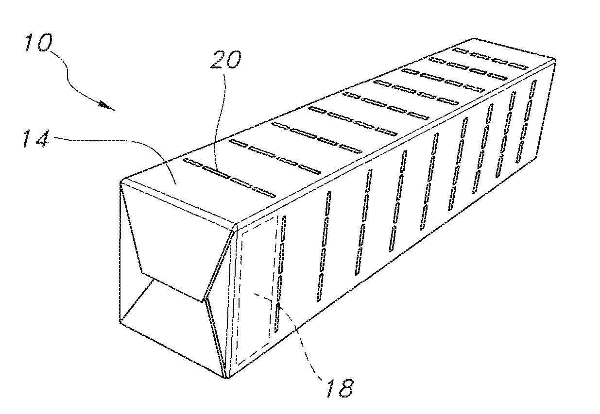
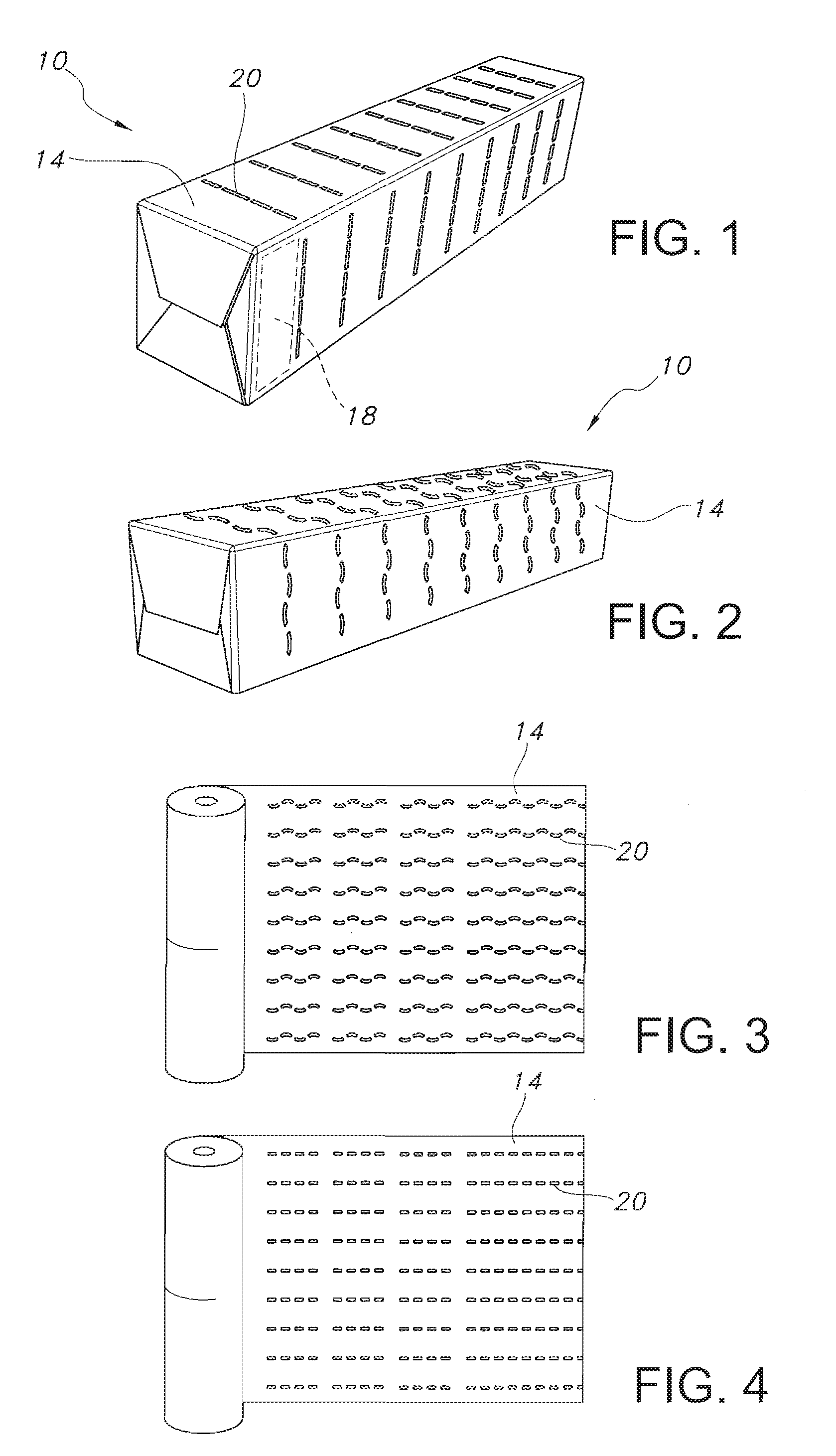
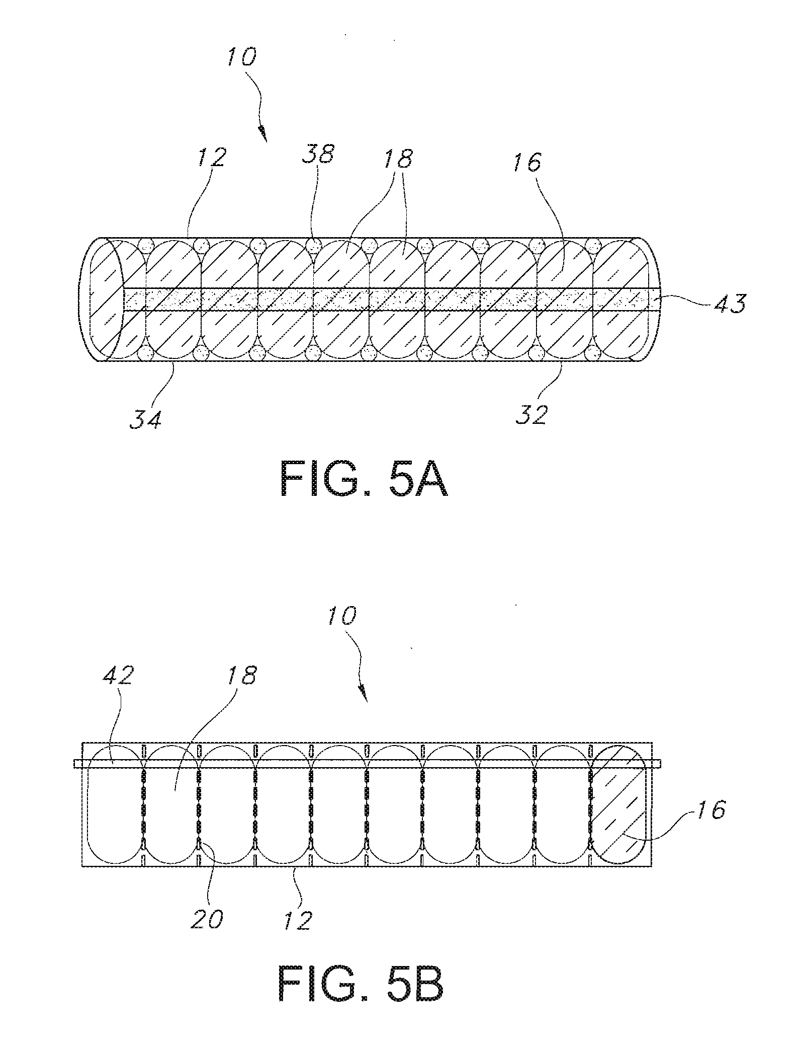
[0022]The present invention provides various embodiments directed to a packaging device for supporting a plurality of consumable product pieces in longitudinal or stacked array, in sealed accommodation. The packaging device provides retaining support for the plurality of consumable product pieces as well as ease in dispensing one or more of the consumable product pieces from the packaging 10. Consumable products or product pieces, as used herein, may include but not be limited to confectionery products, such as gum and candy, lozenges, stacked product pieces, and the like.
[0023]The embodiments of the present invention relate generally to a packaging device for a plurality of consumable product pieces that are arranged and packed in a longitudinally adjacent direction to one another. The packaging device of the present invention allows for the consumable product pieces to be stored and dispensed from their longitudinally adjacent configuration, The packaging device of the present invention also allows a user to remove one or more consumable product pieces from the package in an effective and efficient manner.
[0024]As shown in FIGS. 1 and 2, the packaging device 10 includes an elongate package 12. The elongate package 12 encloses a plurality of adjacent consumable product pieces 18 in a longitudinal array. As additionally shown in FIGS. 3 and 4, the elongate package 12 may be configured from a sheet 14 or substrate which may be used to cover the plurality of pieces 18 in order to promote support and retention of the consumable product pieces therein. The elongate package 12 may be made various types of plastic, as may be desired. The elongate package 12 may be composed of a sheet 14 of plastic or film wrap. While a sheet or film formed of resilient plastic is shown and contemplated herewith, the present invention contemplates employing a sheet of film formed of any material which is generally not readily rupturable, i.e., rupture-resistant, and rendering it rupturable as described hereinbelow. Other materials that may be employed include polyester (PET), metalized polyester (MPET), polyprolylene (OPP), Metalized polypropylene (MOPP), polyethylenes (PE's, including for example LDPE, MDPE, and HDPE), or polyethylene co-polymers (including LUPE, EVA, and surlyn ionomer). Desirable characteristics of the sheet 14 used with the present invention include, for example, quality of barrier material provides, physical properties, sealability, and/or cost effectiveness.
[0025]The sheet 14 may be opaque, translucent, or transparent at one or more areas of the sheet 14, as may be desired. Further, in the case of translucent or transparent portions of the sheet 14, the visual aspects of the sheet 14 may be tinted or color-coded, for example, to correspond to different flavored or colored pieces 18 within. Also, the translucent or transparent portion of the sheet 14 may act as a window to allow a user to view the contents of the package. This may be desirable when the contents of the package have aesthetically pleasing design, including various colors, swirling effects, and the like. Additionally, the sheet 14 may correspond to one or more trademarks, trade names, or brand architecture, as may be desired. As such, the package 10 may be tied to the products or consumables 18 retained inside through one or more of these visual elements,
[0026]As noted above, the sheet 14, and more particularly, the plastic film is generally not readily rupturable and may be formed from a wide variety of materials, such as polyester or polyethylene.. In addition, the sheet 14 may be formed of a single layer or a composite layer of various materials. Where the film is a composite, it may be laminated together or may employ an adhesive.
[0027]After the sheet wrapped around the plurality of longitudinally stacked pieces 18, the sheet may be shrunken to fit tightly over the pieces 18, as may be done with the physical characteristics of the sheet 14 or through the application of heat or hot air to a surface of the sheet 14.
[0028]The plastic sheet 14 is more economical to manufacture and apply to the longitudinal stack of pieces 18 to eliminate the added bulk associated with folding and refolding the dead fold region of excess foil packaging. As plastic film may tend to be resilient and stretch, it may be difficult to break, as by tearing to dispense a consumable from a stack held within a plastic wrapper. The present invention contemplates employing a non-metallic sheet which is generally not readily tearable and rendering it tearable as described hereinbelow.
[0029]The packaging device 10 of the present invention allows a user to efficiently and effectively remove one or more pieces 18 from the elongate package 12 while, inter alia, allowing the user to remove the waste packaging with the pieces 18. Thus, the packaging device 10 of the present invention solves the problem of dead fold packages and the bulk of the waste associated with the dead fold of foil wrappers. As one or more of the pieces 18 is removed from the packaging device 10, so too is the portion of the elongate package 12 that the removed pieces 18 are wrapped in. Thus, as the pieces 18 may be removed from the packaging device 10 of the present invention, the packaging results in a clean edge or severed end of the packaging device. The present embodiments allow and promote a clean edge of the packaging device 10 after one or more pieces 18 may be severed and/or removed therefrom.
[0030]With reference to FIGS. 1-4, preferred embodiments of the packaging device 10 of the present invention include the package 12 having a plurality of longitudinally spaced apart weakened locations. The weakened locations 20 extend perimetrically around the package. As shown in FIG. 1, the weakened locations 20 are positioned between adjacently stacked pieces. The weakened locations are discontinuous, spaced apart and generally parallel. The weakened locations may be formed by various techniques, including but not limited to perforations, score lines, laser cuts and the like. The weakened locations may he a pattern of interrupted, generally linear weakened locations extending straight across the package as shown in FIGS. 1 and 4 or may have a wavy configuration as shown in FIGS. 2 and 3. While the arrangement of the weakened locations 20 shown in FIGS. 1-4 is one preferred embodiment, other arrangements, locations and shapes are within the contemplation of the present invention. Moreover, while the weakened locations are shown as spaced apart locations, this need not be the case. Examples of other embodiments of the weakened locations and their arrangements are shown and described hereinbelow.
[0031]For example, the weakened locations 20 may be feinted by placing perforations partially through the plastic sheet 14. In the alternative, the weakened location 20 may be formed by a laser cut placed partially through the sheet 14. Similarly, any type of scoring by mechanical means, weakening by UV light or electromagnetic radiation, or industrial solvent or chemical treatment, may be employed to form the weakened locations 20 partially through the plastic sheet 14.
[0032]The weakened location 20 may take one or more forms, as may be desired. For example, the weakened location 20 may be interrupted (discontinuous) or continuous. The interrupted weakened locations 20 in the sheet 14 of the elongate package 12 may be the result of chemical treatment to the wrapper, UV radiation or other light treatment, perforation, indentation, or a partial cut, As shown in FIGS. 3 and 4, the weakened locations 20 may be produced on the sheet 14 prior to its formation around the plurality of consumables 18 as the elongate package 12. Also, the weakened locations 20 may be formed on the sheet 14 before it is configured into the elongate packaging 12 or after the packaging device 10 is assembled.
[0033]The weakened locations 20 may be arranged to be placed only partially through the sheet so as to maintain the environmental and sealing capabilities of the sheet 14 placed over the plurality of consumables 18. These weakened locations 20 are sufficiently deep so as to allow a tearable force to rip or sever the sheet 14 upon twisting or tearing the consumable from the packaging device 10, The depth of the weakened location may be selected so as to regulate the amount of force necessary to tear the sheet 14 to sever the elongate package 12 at a desired location. While it is preferred that the weakened locations extend only partially through the sheet, in certain instances where environmental sealing may not be necessary, the weakened locations 20 may extend fully through the elongate package 12.
[0034]As shown in FIGS. 6A-6D, the depth of the weakened location 20 may be selected so as to regulate the amount of force necessary to puncture the sheet 14 at a desired location or tear region.
[0035]In addition, it may be desirable for a user to be able to tactilely line up their grip to the elongate package to accord severing, so the outside 32 of sheet 14 may include the weakened location 20 (FIG. 6A). Alternatively, it may be desirable for a user to feel a continuous smooth outer side 32 of sheet 14, thus the weakened location 20 may be placed on the inside 34 of sheet 14 (FIG. 6B), As may be appreciated, the weakened location 20 may be placed on both sides, either aligned or not aligned as shown in FIGS. 6C and 6D.
[0036]With the weakened location 20 of the elongate package 12, the packaging device 10 need not be peeled back or torn in order to remove or dispense product. Rather, a user may apply pressure to the weakened location, for example, by exerting a twisting or angled force to the entire packaging device 10 in order to remove a portion of the elongate package 12 from the package device 10. Within the removed portion is included one or more pieces 18, along with the removed portion of sheet 14 that was part of the elongate package 12. The user may easily remove a piece 18 from the elongate package 12 while at the same time reducing the size and “dead packaging”, or used waste wrapper, associated with the packaging device 10. One or more consumable pieces may be dispensed at one time. The user simply adjusts their grip to the desired area along the packaging device, and twists accordingly.
[0037]Examples of various arrangements of the weakened locations 20 are shown in FIGS. 11A-11B. It may, however, be appreciated that such examples should not be considered
[0038]The weakened location 20 may line up where two pieces 18 touch or lie adjacent to one another, so that when a user removes one or more consumables from the package 10, a dean edge may result on the edge of the packaging device with the outer edge of one piece 18a. This is depicted, for example, in FIG. 11A. The weakened location 20 may also be configured such that once one or more consumables are removed from the packaging device 10, the outermost piece 18b may sit partially out of the enclosed packaging 12 such that it appears slightly out of the severed sheet 14 line as in FIG. 11B. As shown in FIG. 11C, the weakened region 20 may also be configured such that once one or more pieces are removed from the packaging device 10, the outermost piece 18c sits within the enclosed packaging 12, such that there is a partial lip or edge created by the torn or severed sheet 14 of enclosed packaging 12 that extends beyond the edge of the outermost consumable 18c. Further, as depicted in FIG. 11D, the packaging device 10 may have a weakened location that is non-parallel, such that the removal of one or more pieces 18 from the packaging device 18 may result in the outermost pieces 18 partially protruding from an outer edge of the elongate package 12 in such a manner that a larger portion of either a top or bottom of the piece 18c protrudes from said package. In certain circumstances, it may be desirable for a user to remove at least one piece 18 from the packaging device and have the outermost piece 18 be partially exposed from said enclosed packaging 12 in order to allow a user to grip said piece 18 for a future removal, as may be the case in FIGS. 11B and 11D. It may also be advantageous for the outermost piece to be more protected by said enclosing package 12, as may be the case with configurations depicted in FIGS. 11A and 11C.
[0039]It may be desirable for the package device 10 to further include a tie (not shown), The tie may be used to tie off the end of an open elongate package 12 to prevent undesired materials from entering the elongate package 12 and/or to prevent the consumables 18 from exiting the package. The tie may be composed of one or more desired materials. The tie may be configured onto the elongate package or otherwise movable to as to be reusable as one or more consumables 18 are continually removed from the package 12. The tie may be non-rigid, semi-rigid, or rigid such that the tie may be knotted, twisted, or folded in order to retain the elongate packaging in a closed position.
[0040]The arrangement of FIG. 11D also shows the weakened location 20 to be longitudinally continuous along the length of package 12, rather than discontinuous and spaced apart as shown in. FIGS. 1-4 and 11A-11C.
[0041]It should be noted that though the weakened region 20 depicted in FIGS. 11A through 11D may take one or more of the forms, including continuous or discontinuous. Moreover, the weakened locations may be parallel, perpendicular, or placed in a pattern or configuration, as may be desired in order to promote a tear region at a particular site once a predetermined level of force is applied to the packaging device 10.
[0042]Also, with the removal of the packaging along with the pieces, there is no longer any dead packaging that the user must carry around with the remainder of the non-consumed consumables. Thus, the user need not rustle or make noise with the dead fold packaging in order to remove future consumables from the package. So, the packaging device of the present invention is less noisy than dead fold type packages.
[0043]As shown in Figures SB, weakened location 20 may further include one or more tear strips 42. The tear strip 42 may extend longitudinally along the length of package 12 or may be perimetrically wound around the package 12 in similar manner as shown in FIGS. 11A through 11D, replacing the weakened location 20 shown therein. In such an instance, one or more individual tear strips 42 may be employed, as may be desired.
[0044]The tear strip 42 may be accompanied by one or more weakened locations 20, in one or more patterns or configurations as may be desired. In use, the tear strip may allow a user to tear a portion of the elongate package in order to remove the piece 18 from the elongate package prior to consumption. The tear strip 42 may be partially torn through the elongate package 12 either prior to or subsequent to the manual force that may be applied by a user to separate one or more pieces 18 from said packaging device 10. Thus, the tear strip 42 may aid a user in removing one or more pieces from the enclosing package 12, which may securely otherwise encase the consumable once it is severed from the main packaging device 10.
[0045]This is particularly beneficial, for example, when the pieces 18 are individually wrapped with a wrapper. When the pieces 18 are individually wrapped, each piece 18 may be protected from environmental concerns, so a complete region extending through the sheet 14 from the inside 34 to the outside 32 of sheet 14 may be employed. As each of the pieces 18 may be individually wrapped with wrapper 16, the user may discard the wrapper 16 along with the removed portion of the elongate package 12.
[0046]As shown in FIGS. 7 and 9, one technique for providing the weakened locations 20 is to place score lines 22 or perforations directly at the site where the edges of the consumables 18 are adjacent to one another. As discussed with respect to FIGS. 11A through 11C, the score lines or perforations may be arranged in various positions with respect to pieces 18.
[0047]Other forms of the weakened locations may include tearable dots or other shapes 28 placed between each consumable 18 in the elongate package 12. For example, patterns and shapes such as an X pattern, dots, or letters may be provided as shown in FIGS. 8 and 10. Of course, other shaped patterns may also be employed. Similarly, a plurality of parallel or nonparallel lines 26 may be placed in the preformed sheet 14 or onto the elongate package 12.
[0048]The various embodiments of the packaging device 10 of the present invention may further include a means for retaining the pieces 18 within the elongate package 12. The retaining means may include, for example, releasably bonding the pieces 18 to the inner surface 34 of the sheet 14. In such a manner, the bond may be selected from one or more of adhesives, heat seals, and combinations thereof. Various glues or adhesives may be employed, as may be desired. The adhesive may be edible in the case where the adhesive is directly contacting the unwrapped pieces 18. Alternatively, the adhesive or hot seal may be administered to the wrapper 16 of the consumable 18, in instances where each consumable 18 is individually wrapped within the elongate wrapper 16.
[0049]The adhesive or other adhering means may be administered on a line 43 along the length of the inner wall 34 (as shown in FIG. 5A) and/or as dabs 38 along the inner wall 34 in order to secure each of the plurality of pieces 18 to the package 12. In such a manner, once the elongate package 12 is severed and at least one consumable 18 is removed therefrom, the remainder of the pieces 18 remain retained within the package 12 unless and until the proper tearing force is applied externally to the package 12 to sever and/or remove additional pieces 18 therefrom.
[0050]Moreover, the art is replete with examples of different configurations, styles and arrangements to perforations which facilitate puncturing, tearing or ripping of various substrates. One, more, or a combination of these examples may be likewise employed with the various embodiments of the present invention. Reference is made to the following U.S. patents and publications, all of which are incorporated by reference herein for all purposes: U.S. Pat. Nos. 3,583,558; 5,041,317; 5,496,605; 5,616,387; 6,105,776; 6,213,132; 6,277,459; 6,983,857; 7,011,226; 7,138,169; 7,311,649; and U.S. Patent Application Publication No. 2005/0156018.
[0051]As may be seen by the above-referenced patents and publications, the configuration, arrangement and location of perforations may be selected for enhancing the ability of the sheet to rupture or rip or may be selected for aesthetic or manufacturing requirements.
[0052]Various changes to the foregoing described and shown structures would now be evident to those skilled in the art. Accordingly, the particularly disclosed scope of the invention is set forth in the following claims.
PUM
Property | Measurement | Unit |
Length | ||
Shape |
Description & Claims & Application Information
We can also present the details of the Description, Claims and Application information to help users get a comprehensive understanding of the technical details of the patent, such as background art, summary of invention, brief description of drawings, description of embodiments, and other original content. On the other hand, users can also determine the specific scope of protection of the technology through the list of claims; as well as understand the changes in the life cycle of the technology with the presentation of the patent timeline. Login to view more.