Dialysis device with flow-channel structure for capillary-driven fluidic propulsion without trapped air bubbles

US20110312675A1Inactive Publication Date: 2011-12-22GENEASYS
1 Cites 0 Cited by

Patent Information

Authority / Receiving Office
US · United States
Current Assignee / Owner
Publication Date
2011-12-22
Estimated Expiration
Not applicable · inactive patent

Smart Images

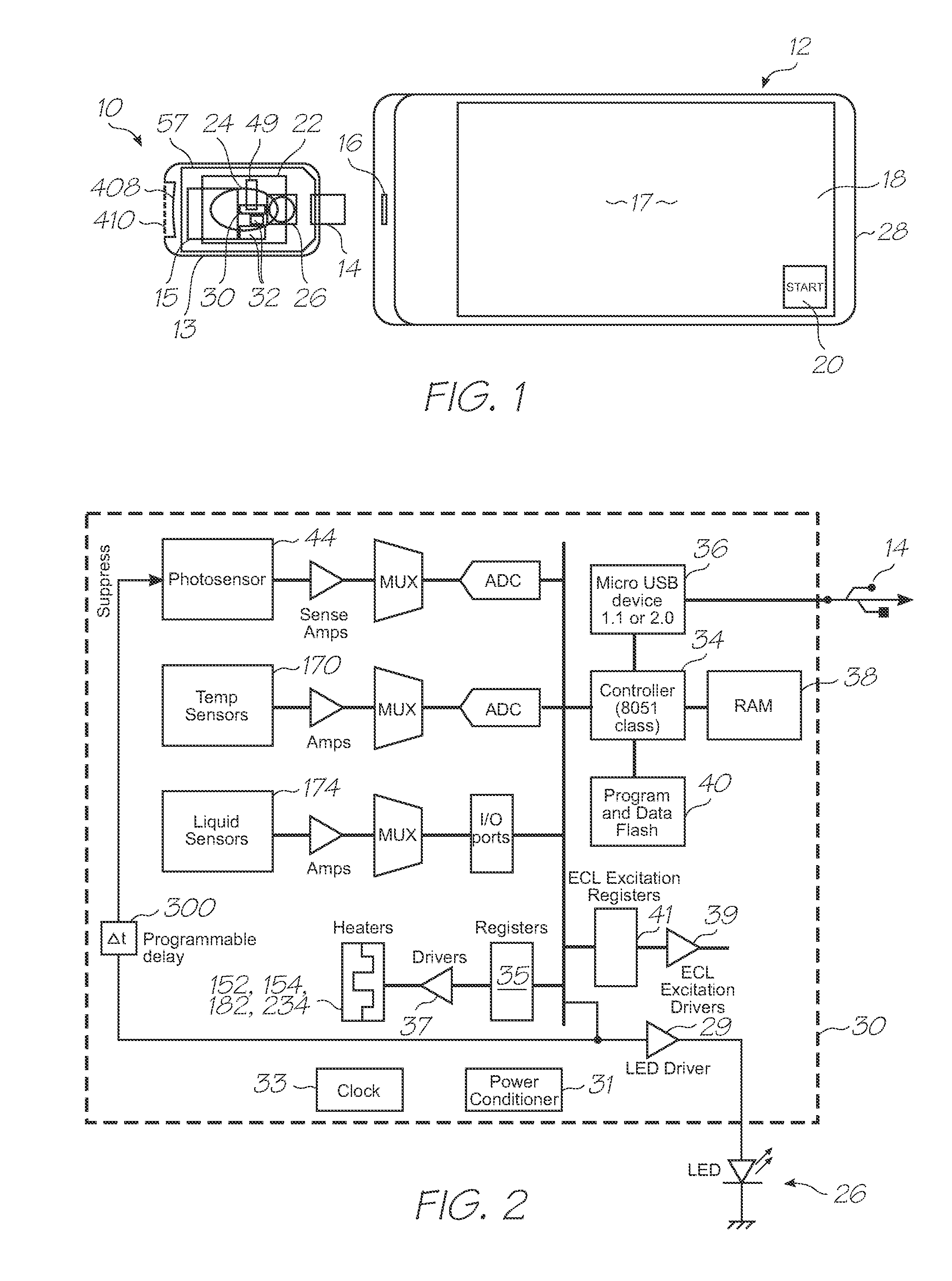
  • Figure 1
    Figure 1
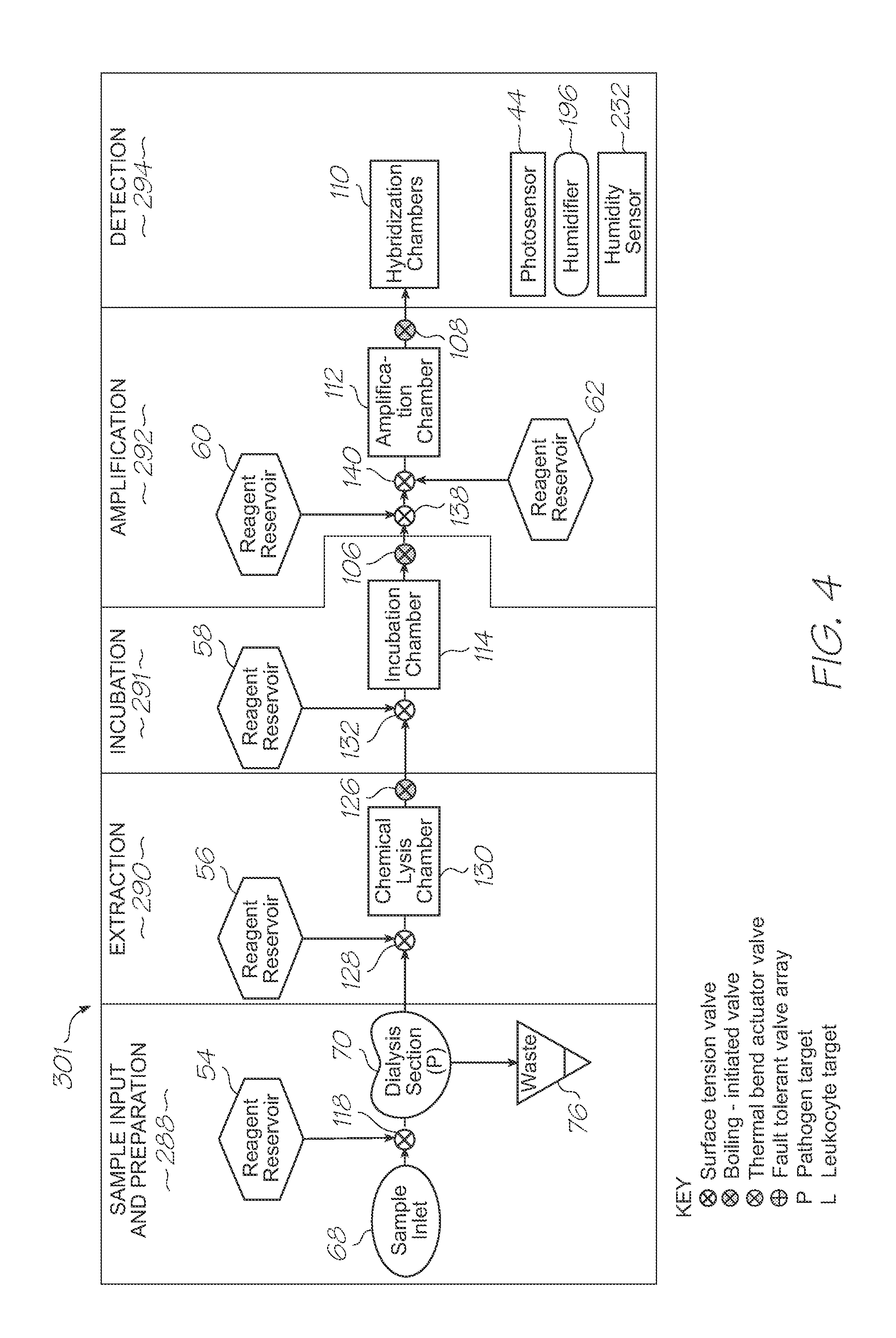
  • Figure 2
    Figure 2
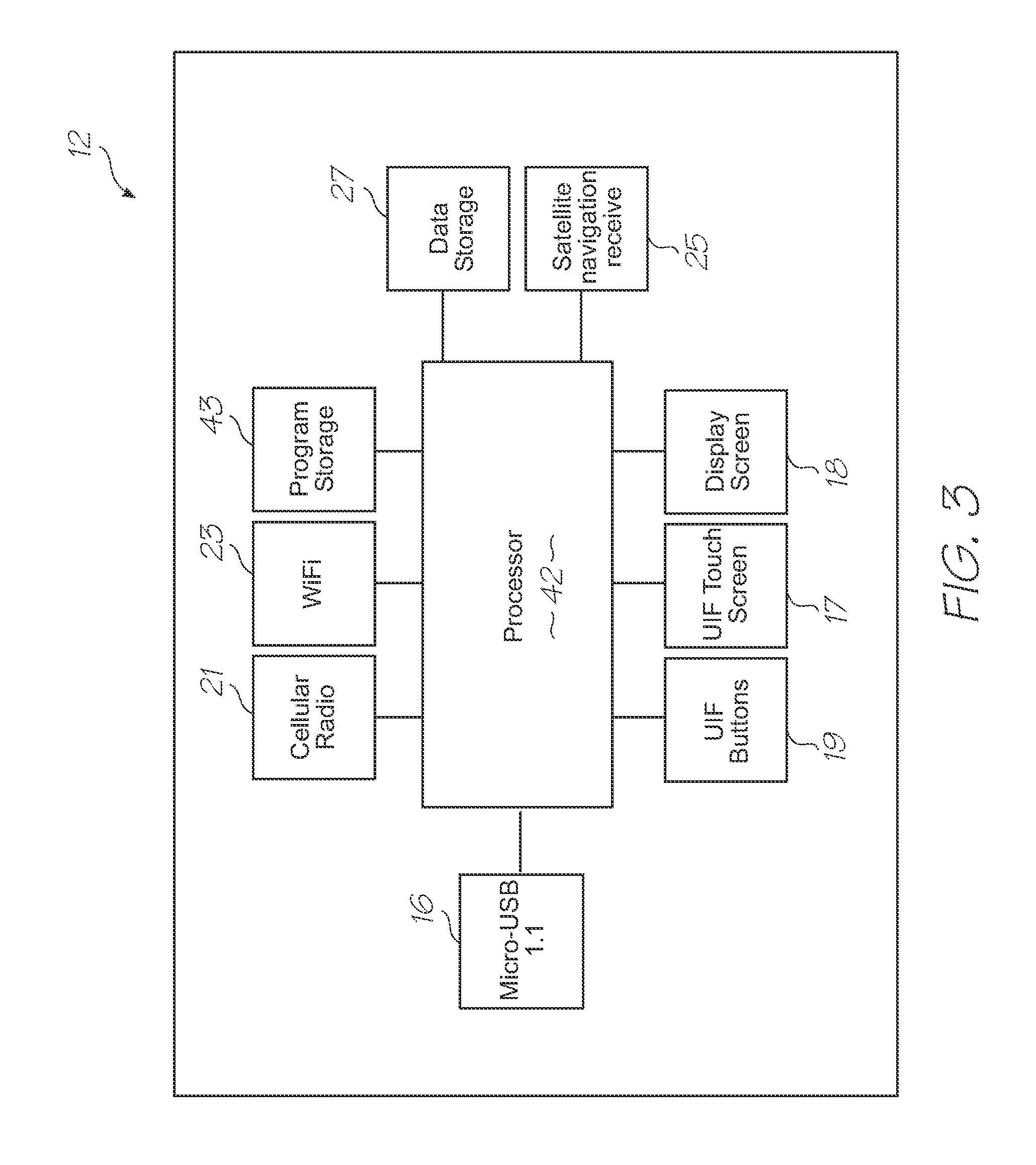
  • Figure 3
    Figure 3
Patent Text Reader

Abstract

A dialysis device with capillary-driven, flow-channel structure for dialysis of a fluid containing constituents of different sizes, the dialysis device having a first channel configured to fill with the fluid by capillary action, a second channel configured to fill with the fluid by capillary action, a plurality of fluid connections between the first channel and the second channel, each of the fluid connections being configured to pin a meniscus of the fluid that arrests capillary flow between the first channel and the second channel, a bypass channel between the first channel and the second channel, the bypass channel joining the second channel upstream of the plurality of fluid connections and is configured for uninterrupted capillary driven flow from the first channel to the second channel, wherein during use, flow from the bypass channel reaches the meniscus pinned at each of the fluid connections after the meniscus has formed such that the flow sequentially removes each of the menisci and sample flow from the first channel to the second channel is via the plurality of fluid connections as well as the bypass channel.
Need to check novelty before this filing date? Find Prior Art

Description

FIELD OF THE INVENTION

[0001] The present invention relates to diagnostic devices that use microsystems technologies (MST). In particular, the invention relates to microfluidic and biochemical processing and analysis for molecular diagnostics.CO-PENDING APPLICATIONS

[0002] The following applications have been filed by the Applicant which relate to the present application:GBS001USGBS002USGBS003USGBS005USGBS006USGSR001USGSR002USGAS001USGAS002USGAS003USGAS004USGAS006USGAS007USGAS008USGAS009USGAS010USGAS012USGAS013USGAS014USGAS015USGAS016USGAS017USGAS018USGAS019USGAS020USGAS021USGAS022USGAS023USGAS024USGAS025USGAS026USGAS027USGAS028USGAS030USGAS031USGAS032USGAS033USGAS034USGAS035USGAS036USGAS037USGAS038USGAS039USGAS040USGAS041USGAS042USGAS043USGAS044USGAS045USGAS046USGAS047USGAS048USGAS049USGAS050USGAS054USGAS055USGAS056USGAS057USGAS058USGAS059USGAS060USGAS061USGAS062USGAS063USGAS065USGAS066USGAS067USGAS068USGAS069USGAS070USGAS080USGAS081USGAS082USGAS083USGAS084USGAS085USGAS086USGAS087USGAS...

Examples

Embodiment Construction

Overview

[0213]This overview identifies the main components of a molecular diagnostic system that incorporates embodiments of the present invention. Comprehensive details of the system architecture and operation are set out later in the specification.

[0214]Referring to FIGS. 1, 2, 3, 85 and 86, the system has the following top level components:

[0215]Test modules 10 and 11 are the size of a typical USB memory key and very cheap to produce. Test modules 10 and 11 each contain a microfluidic device, typically in the form of a lab-on-a-chip (LOC) device 30 preloaded with reagents and typically more than 1000 probes for the molecular diagnostic assay (see FIGS. 1 and 85). Test module 10 schematically shown in FIG. 1 uses a fluorescence-based detection technique to identify target molecules, while test module 11 in FIG. 85 uses an electrochemiluminescence-based detection technique. The LOC device 30 has an integrated photosensor 44 for fluorescence or electrochemiluminescence detection (de...