Retractable Rod Structure

Inactive Publication Date: 2012-01-05
PENG I SIN
View PDF2 Cites 10 Cited by
  • Summary
  • Abstract
  • Description
  • Claims
  • Application Information

AI Technical Summary

Benefits of technology

[0005]The primary object of the present invention is to provide a retractable rod structure which comprises an inner pipe, an outer pipe and a positioning unit. The positioning unit comprises a sleeve and a resilient engaging plate. The sleeve has an upper portion and a lower portion in different diameters to receive the inner pipe and the outer pipe, respectively. An annular stop portion is provided between the upper portion and the lower portion to hold against a top edge of the outer pipe. The sleeve has a side wall formed with a first threaded hole and a second threaded hole for engagement of a positioning bolt and a fixing bolt. The sleeve further has a pair of grooves formed on an inner wall of the sleeve close to two sides of the first threaded hole and the second threaded hole. The resilient engaging plate has a curved portion corresponding to the inner pipe and a pair of flanges extending from two sides of the curved portion. By turning the positioning bolt clockwise or counterclockwise, the resilient engaging plate is controlled to engage with or disengage from the inner pipe for adjustment of the inner pipe. The present invention provides a stepless positioning effect, without wearing the retractable rod, and can be used as a multi-function retractable rod.

Problems solved by technology

The distal end of the positioning bolt is screwed to hold against the inner pipe so as to position the inner pipe in place, which may scrape and damage the inner pipe.
Besides, it is not easy to position the inner pipe because the contact area is small.

Method used


Image

  • Retractable Rod Structure
  • Retractable Rod Structure
  • Retractable Rod Structure

Examples


Embodiment Construction

[0011]Embodiments of the present invention will now be described, by way of example only, with reference to the accompanying drawings.

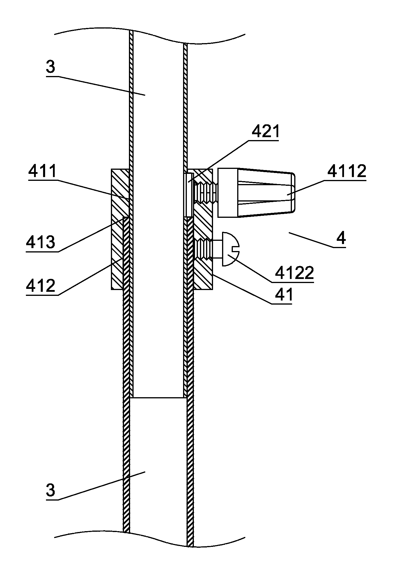
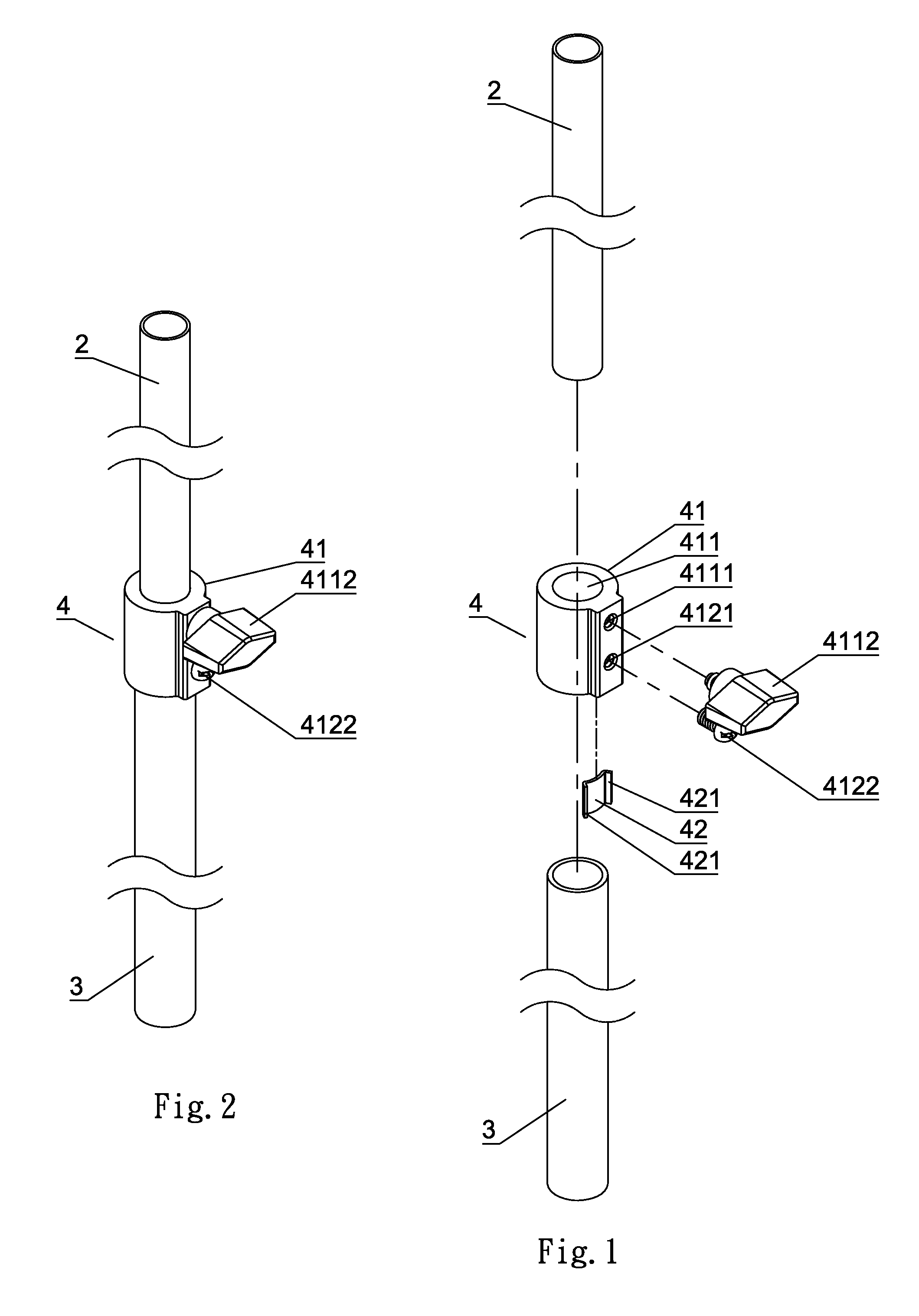
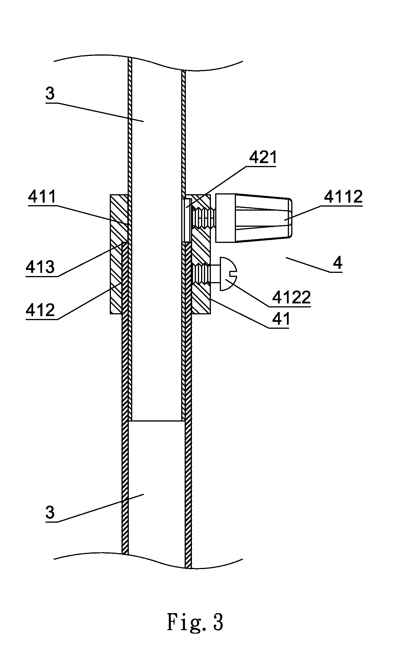
[0012]As show in FIG. 1, FIG. 4 and FIG. 5, a retractable rod structure according to a preferred embodiment of the present invention comprises an inner pipe 2, an outer pipe 3, and a positioning unit 4. The inner pipe 2 has an upper end coupled with a connection member and a lower end inserted in the outer pipe 3. The positioning unit 4 is adapted to position the inner pipe 2 and the outer pipe 3 to become a retractable rod.

[0013]The connection member on top of the inner pipe 2 can be canvas, a boat lamp, a boat oar, a hook or the like. The inner pipe 2 has an outer diameter slightly smaller than the inner diameter of the outer pipe 3, so that the inner pipe 2 can be retracted in the positioning unit 4 and the outer pipe 3. The positioning unit 4 provides a positioning effect to secure the inner pipe 2 and the outer pipe 3.

[0014]The outer pipe 3 has a...


PUM


Abstract

A retractable rod structure includes an inner pipe, an outer pipe and a positioning unit. The positioning unit includes a sleeve and a resilient engaging plate located in the sleeve. The sleeve has a side wall formed with a first threaded hole and a second threaded hole for engagement of a positioning bolt and a fixing bolt. The sleeve further has a pair of grooves formed on an inner wall of the sleeve close to two sides of the first threaded hole and the second threaded hole. By turning the positioning bolt clockwise or counterclockwise, the resilient engaging plate is controlled to engage with or disengage from the inner pipe for adjustment of the inner pipe. The present invention provides a stepless positioning effect, without wearing the retractable rod, and can be used as a multi-function retractable rod.

Description

BACKGROUND OF THE INVENTION[0001]1. Field of the Invention[0002]The present invention relates to a retractable rod structure, and more particularly to one having a resilient engaging plate disposed in a positioning unit. By turning a positioning bolt, an inner pipe is retractable relative to an outer pipe, without wearing the inner pipe and providing a larger contact area to secure the inner pipe.[0003]2. Description of the Prior Art[0004]A conventional retractable rod comprises an inner pipe, an outer pipe and a positioning unit to connect the inner pipe and the outer pipe together. By turning the positioning unit clockwise or counterclockwise, the inner pipe is controlled to extend out or retract into the outer pipe for adjusting the length of the retractable rod. There is a gap between the inner pipe and the outer pipe for pulling or pushing the inner pipe. The distal end of the positioning bolt is screwed to hold against the inner pipe so as to position the inner pipe in place, ...

Claims


Application Information

Patent Timeline
IPC IPC(8): F16L27/00
CPCF16B7/1472F16M2200/027F16M11/28
Inventor PENG, I-SIN
Owner PENG I SIN
Why Eureka
Try Eureka