Liquid-jet head and liquid-jet apparatus having same

a liquid-jet recording and liquid-jet head technology, which is applied in the direction of printing and inking apparatus, etc., can solve the problems of insufficient ejection of ink droplets, low ink absorption of conventional ink targeted at paper, etc., and achieve the effect of high-speed printing and adequate ejection

Inactive Publication Date: 2012-01-19
SEIKO EPSON CORP
View PDF1 Cites 1 Cited by
  • Summary
  • Abstract
  • Description
  • Claims
  • Application Information

AI Technical Summary

Benefits of technology

[0017]An advantage of some aspects of the invention is to provide a liquid-jet head, which can ensure an adequate amount of ejection even when using a highly viscous liquid, and can impart a satisfactory meniscus behavior after ejection to contribute to high speed printing, and a liquid-jet apparatus having the liquid-jet head.
[0019]According to this aspect, the structures of the liquid supply path and the nozzle orifice are determined, with the passage resistances of the liquid supply path and the nozzle orifice being set in appropriate relationship, in addition to the well known finding that the ejection characteristics of a liquid vary with the ratio between the inertance of the liquid supply path and the inertance of the nozzle orifice. Thus, even when a highly viscous liquid is used, an adequate amount of ejection of the liquid can be ensured, and satisfactory return of meniscus after ejection can be obtained. As a result, the printing quality of printing products obtained by use of the high viscosity liquid can be kept satisfactory, and a contribution to high speed printing can be made.
[0020]The liquid-jet head becomes even more preferred, if it uses the liquid whose viscosity is 8.0 (mPa·s) or higher. In this case, desired satisfactory printing can be done even on plastics having a smooth surface and having no absorbency. Particularly, it is preferred for the liquid to have a viscosity of 8.0 (mPa·s) or higher, but 20.0 (mPa·s) or lower. In this case, an adequate amount of ejection of the liquid can be ensured, and satisfactory return of meniscus after ejection can be achieved. Moreover, the relationship between the passage resistances R1 and R2 is desired to be 3×R1≦R2≦20×R1. By so doing, an adequate amount of ejection of the liquid can be ensured, and satisfactory return of meniscus after ejection can be achieved.
[0021]Furthermore, the liquid-jet head is preferably configured such that when the cross-sectional area of the liquid supply path is designated as S1, and the cross-sectional area of the liquid ejection port of the nozzle orifice is designated as S2, the relationship S2<S1 holds. In this case, the aforementioned inertances M1 and M2 and the passage resistances R1 and R2 can be easily brought into the predetermined relationships as described above.

Problems solved by technology

Conventional ink targeted at paper, etc., however, is not fully effective for objects of printing having a low ink absorption, such as plastics.
That is, if ink targeted for paper is printed, for example, on a plastic, the viscosity of the paper-targeted ink (a viscosity, for example, of the order of 3.5 (mPa·s) at ordinary temperature) is too low to be printed on the plastic, presenting the problem that an ink droplet flows after landing on the object of printing.
Conventionally, however, the high viscosity ink has merely been used, and the structure of the ink-jet recording head itself has not been changed.
When printing is performed using high viscosity ink by the ink-jet recording head according to the related art, however, the following problems have occurred: The amount of the ink droplet ejected through the nozzle orifice is so small that printing quality is adversely affected.
This has been an impediment to high speed printing.
Such problems exist not only with an ink-jet recording head which ejects ink, but also with a liquid-jet head which jets a liquid other than ink.
Liquid-jet heads for use in industrial applications other than printing, in particular, have many opportunities to jet a highly viscous liquid, and have the above problems becoming manifest.

Method used


Image

  • Liquid-jet head and liquid-jet apparatus having same
  • Liquid-jet head and liquid-jet apparatus having same
  • Liquid-jet head and liquid-jet apparatus having same

Examples


first embodiment

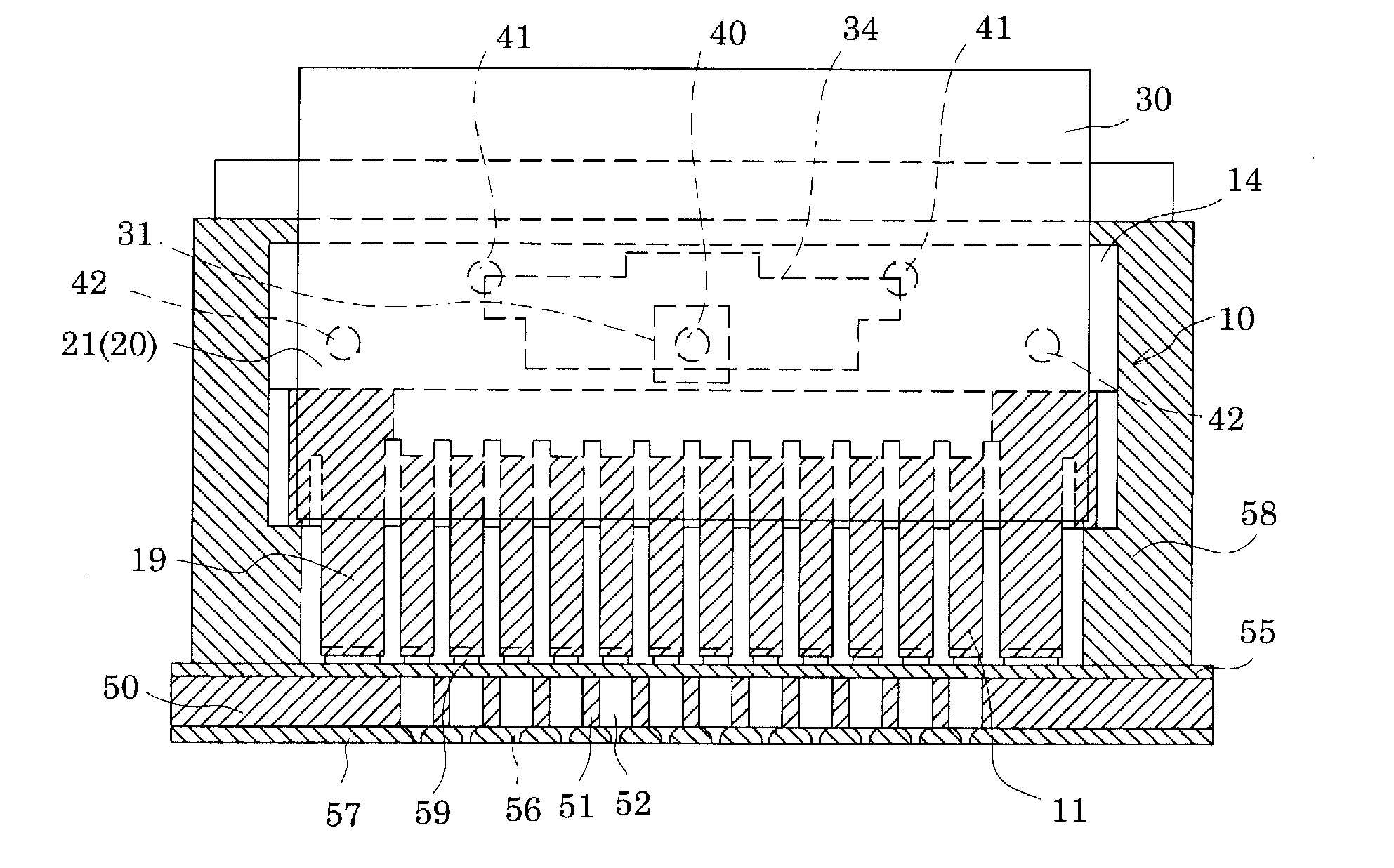
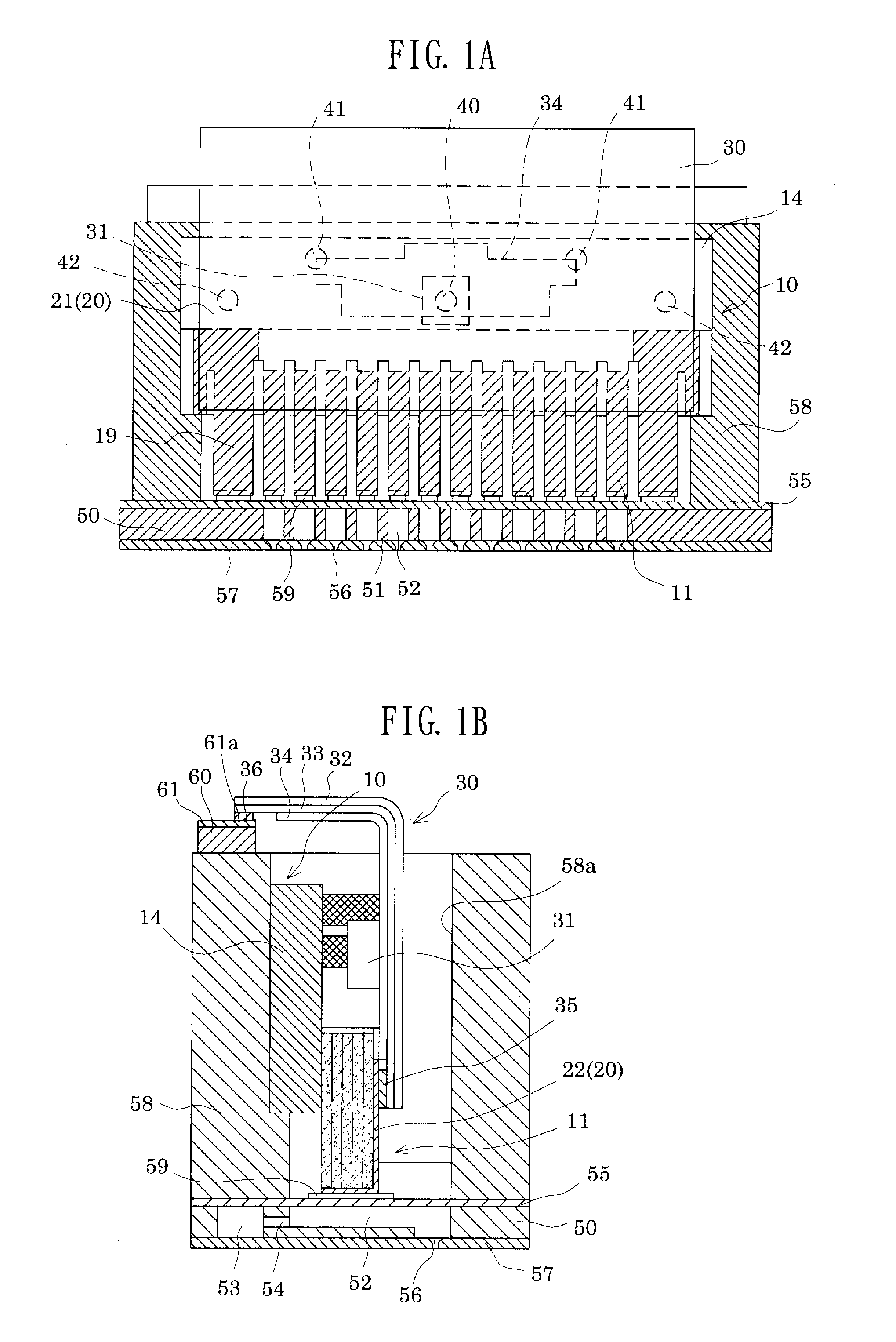
[0050]FIG. 1A is a sectional view, in a transverse direction (a direction perpendicular to a longitudinal direction), of a pressure generating chamber of an ink-jet recording head which is an example of a liquid-jet head according to an embodiment of the invention. FIG. 1B is a sectional view, in the longitudinal direction, of the pressure generating chamber of the ink-jet recording head which is an example of the liquid-jet head. As shown in these drawings, a passage-forming substrate 50 consists of a single crystal silicon substrate. In a surface layer portion on one side of the passage-forming substrate 50, pressure generating chambers 52 defined by a plurality of compartment walls 51 are arranged parallel in the width direction (transverse direction) of the passage-forming substrate 50. A reservoir 53 for supplying ink, a type of a liquid, to each pressure generating chamber 52 is in communication with one end portion, in the longitudinal direction, of each pressure generating c...


PUM


Abstract

A liquid-jet head comprising a pressure generating chamber, which is supplied with a liquid via a liquid supply path and in which a nozzle orifice for jetting the liquid is formed, and a pressure generator for causing a pressure change within the pressure generating chamber, wherein when an inertance and a passage resistance of the liquid supply path are designated as M1 and R1, respectively, and an inertance and a passage resistance of the nozzle orifice are designated as M2 and R2, respectively, relationships M2<M1 and R2>2×R1 hold.

Description

CROSS REFERENCE TO RELATED APPLICATIONS[0001]This application is a Continuation application of U.S. patent application Ser. No. 12 / 013,061 filed Jan. 11, 2008, which claims priority from Japanese Patent Application Nos. 2007-005030 filed Jan. 12, 2007, 2007-325193 filed Dec. 17, 2007 and 2008-001268 filed Jan. 8, 2008; the entire disclosures of the prior applications are expressly incorporated by reference herein.BACKGROUND[0002]1. Technical Field[0003]The present invention relates to a liquid-jet head and a liquid-jet apparatus having the liquid-jet head, which are useful particularly when applied in using a highly viscous liquid.[0004]2. Related Art[0005]An example of a liquid-jet apparatus is an ink-jet recording apparatus including an ink-jet recording head equipped with a plurality of pressure generating chambers for generating pressure for ink droplet ejection by a pressure generator comprising a piezoelectric element, an ink supply path for supplying ink individually to each ...

Claims


Application Information

Patent Timeline
Patent Type & Authority Applications(United States)
IPC IPC(8): B41J2/045
CPCB41J2/14274B41J2202/11B41J2202/03
Inventor ZHANG, JUNHUA
Owner SEIKO EPSON CORP
Why Eureka
Try Eureka