Gangway bearing retainer plate

Active Publication Date: 2012-01-26
SAFERACK
View PDF6 Cites 5 Cited by
  • Summary
  • Abstract
  • Description
  • Claims
  • Application Information

AI Technical Summary

Problems solved by technology

The process requires a relatively substanti

Method used


Image

  • Gangway bearing retainer plate
  • Gangway bearing retainer plate
  • Gangway bearing retainer plate

Examples


Embodiment Construction

[0018]Reference will now be made in detail to presently preferred embodiments of the invention, one or more examples of which are illustrated in the accompanying drawings. Each example is provided by way of explanation of the invention, not limitation of the invention. In fact, it will be apparent to those skilled in the art that modifications and variations can be made in the present invention without departing from the scope or spirit thereof. For instance, features illustrated or described as part of one embodiment may be used on another embodiment to yield a still further embodiment. Thus, it is intended that the present invention covers such modifications and variations as come within the scope of the appended claims and their equivalents.

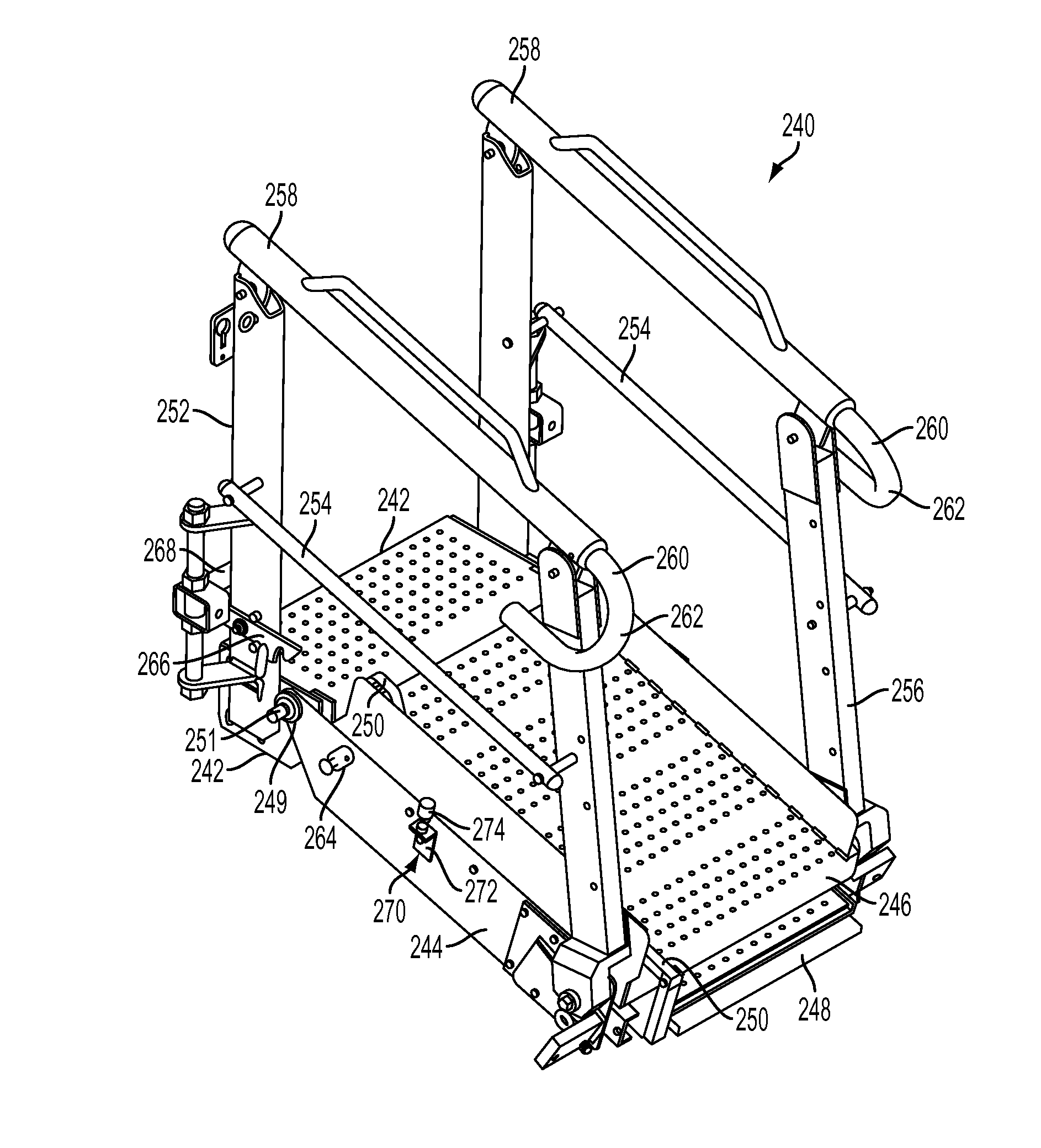
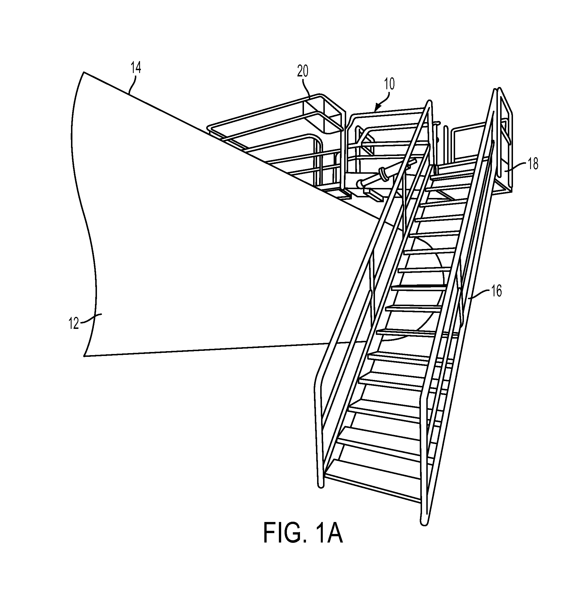
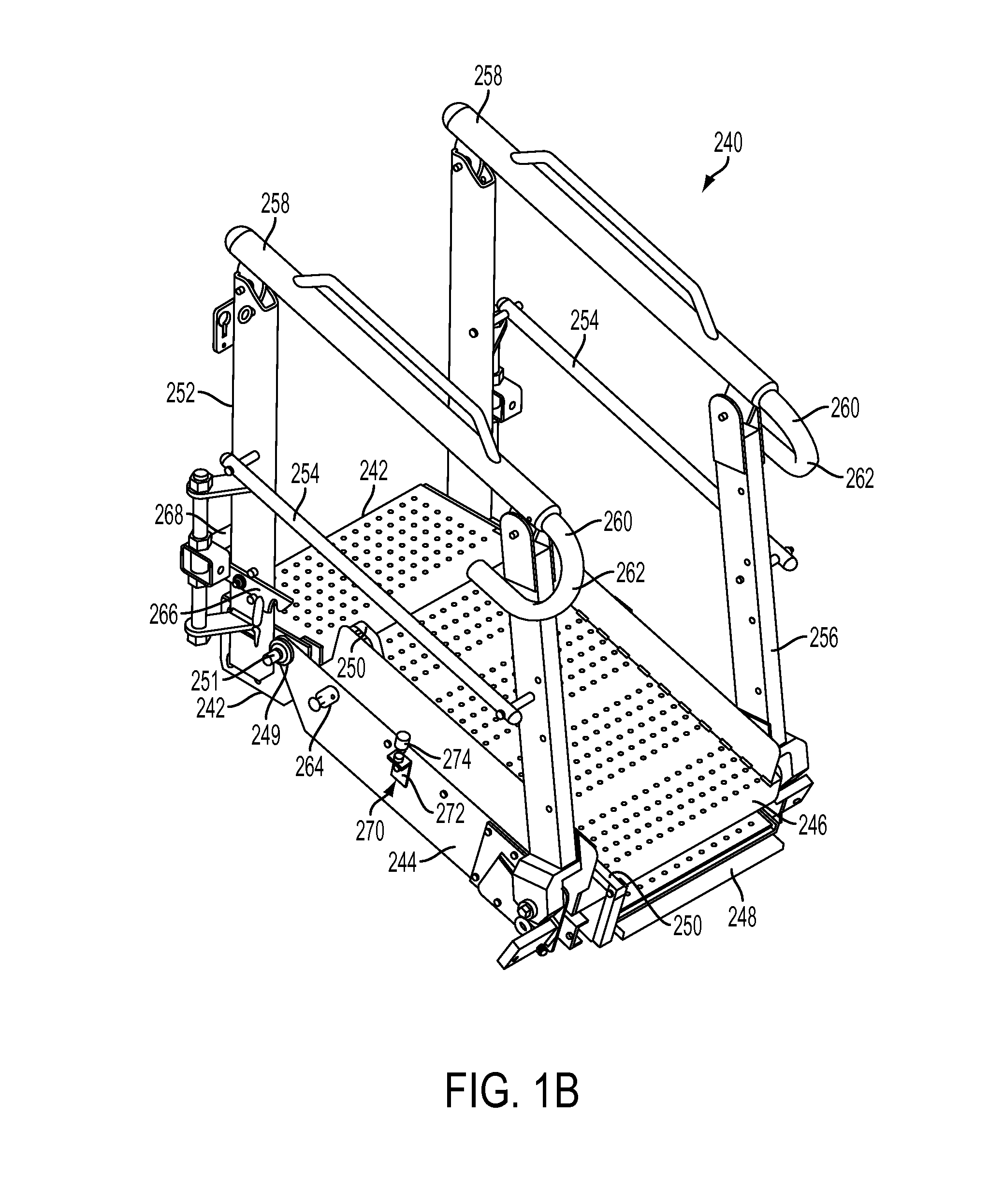
[0019]FIG. 1A illustrates the placement of a gangway 10 to provide access to a storage container 12 from above. Storage container 12 typically contains material, such as particulate matter, to be unloaded from the container's top indicated at ...


PUM


Abstract

A bearing retainer plate for fall restraint equipment made from a single, continuous piece of sheet metal, where the metal is lasered, cut, and/or butterflied to define a plurality of apertures. A bearing, preferably possessing a self-centering characteristic, is inserted into one of the apertures, while an adapter or bracket for an over-travel stop is inserted into another. A foot lock stud is inserted into another aperture defined by the bearing retainer plate and welded into place. The piece of metal may also define apertures configured to receive fasteners for attaching the plate to the fall restraint equipment, such as to a support structure of a gangway.

Description

CROSS-REFERENCE TO RELATED APPLICATIONS[0001]This application claims the benefit of U.S. Patent Application Ser. No. 61 / 366,612, entitled “Gangway Bearing Retainer Plate” and filed on Jul. 22, 2010, the entire disclosure of which is hereby incorporated by reference as if set forth verbatim herein and relied upon for all purposes.FIELD OF THE INVENTION[0002]The present invention relates to fall restraint equipment, and more particularly, to a bearing retainer plate for a gangway.BACKGROUND OF THE INVENTION[0003]Fall restraint equipment, such as gangways, may comprise platforms, ramps, bridges, steps, guardrails, and other support structures. Gangways may be used to provide access to an area, such as the top of a storage container. For example, a semi-trailer truck or a railroad carriage transporting dry goods may need to be unloaded from the container's top. A gangway is used to provide workers a path to unload the material. The major parts of current gangways are constructed by a pr...

Claims


Application Information

Patent Timeline
IPC IPC(8): B65G69/28B23P11/00F16M13/00
CPCB63B27/14Y10T29/49826F16C35/00F16C2326/30
Inventor HONEYCUTT, ROBERT W.
Owner SAFERACK
Why Eureka
Try Eureka