Image pickup apparatus

a technology of image pickup and apparatus, applied in the direction of electrical apparatus, television system details, television systems, etc., can solve the problem of giving the viewer a sense of strangeness

Inactive Publication Date: 2012-03-22
PANASONIC CORP
View PDF11 Cites 8 Cited by
  • Summary
  • Abstract
  • Description
  • Claims
  • Application Information

AI Technical Summary

Benefits of technology

[0007]The present invention has been made in view of those problems, and an object of the present invention is therefore to provide an image pickup apparatus capable of pro...

Problems solved by technology

However, because a 3D picture is seen through a process in which the human brain recognizes a picture formed from parallax images as a three-dimensional image, images seen with eyes that are not adjusted properl...

Method used


Image

  • Image pickup apparatus
  • Image pickup apparatus
  • Image pickup apparatus

Examples


first embodiment

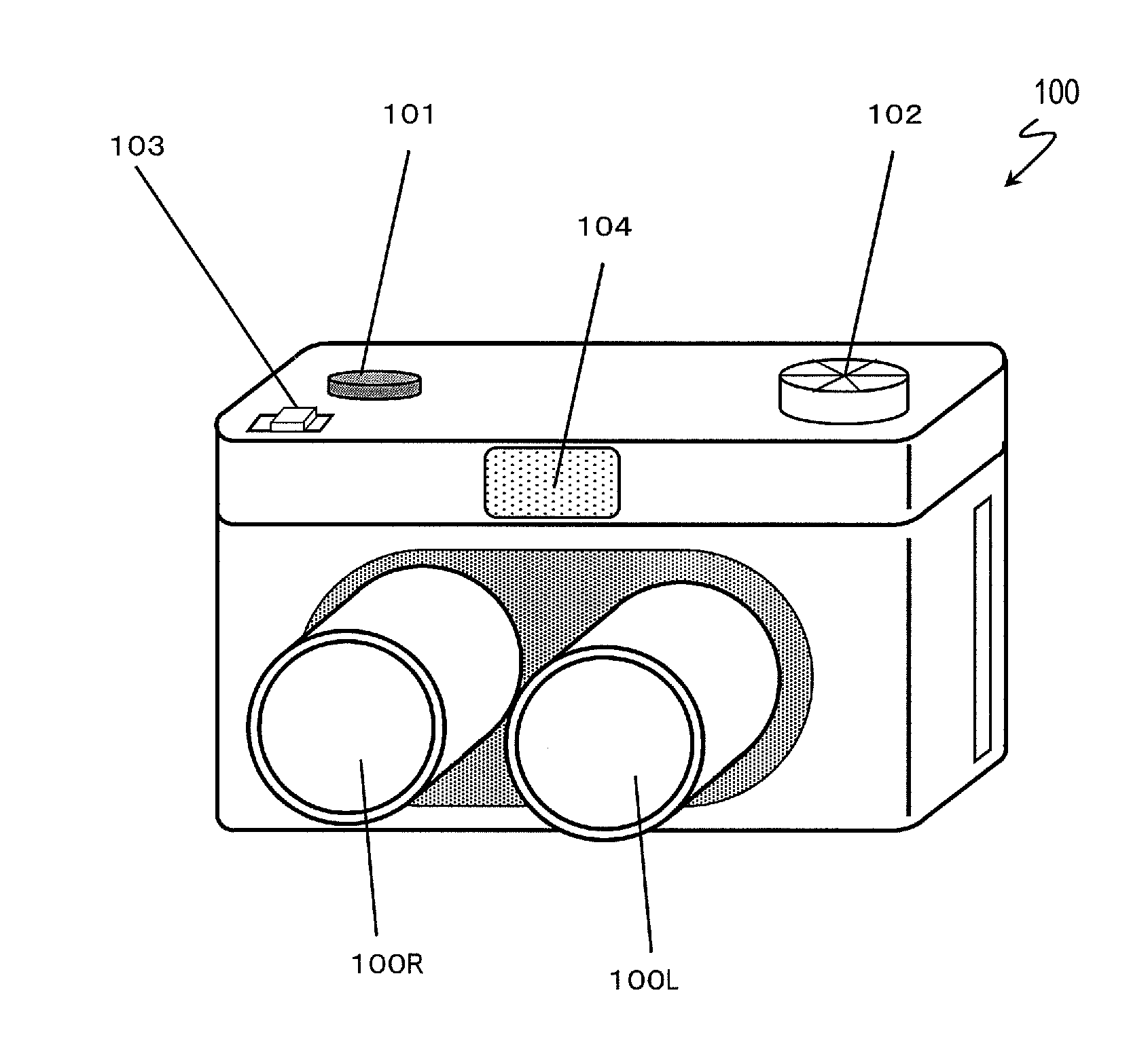
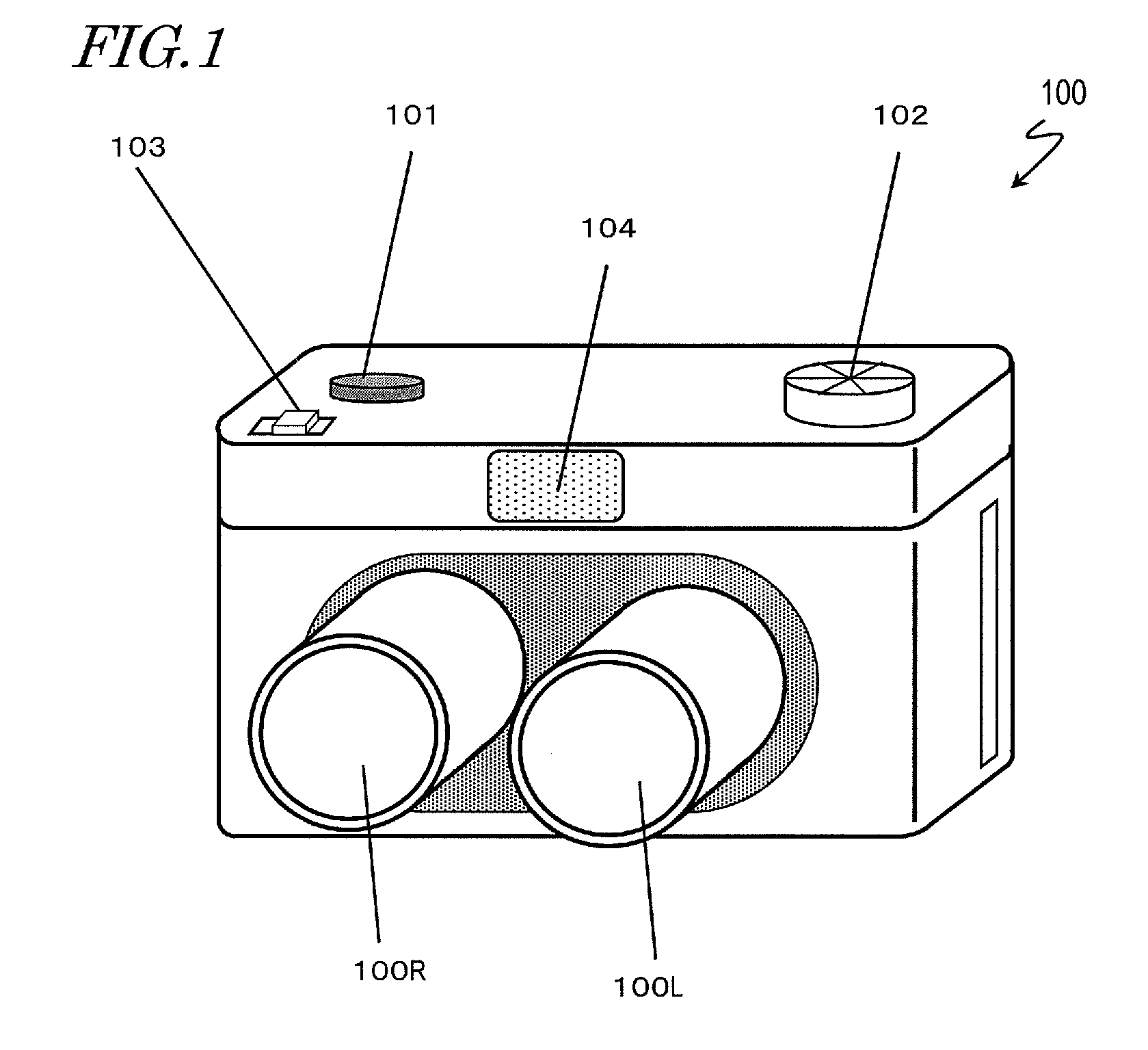
[0056]FIG. 1 is a diagram illustrating the exterior of an image pickup apparatus 100 according to a first embodiment of the present invention. The image pickup apparatus 100 of FIG. 1 includes two imaging lenses, which are respectively denoted by 100R (the lens on the right side as a person holding the image pickup apparatus 100 faces a subject) and 100L (the one on the left side as a person holding the image pickup apparatus 100 faces a subject), a video recording ON / OFF switch 101, a mode switching switch 102, a zoom lever 103, and a strobe 104.

[0057]The image pickup apparatus 100 takes a 3D picture based on two lateral (left-right) parallax images which are obtained via the two imaging lenses 100R and 100L. This image pickup apparatus 100 is also capable of taking a 2D picture using an image that is taken with only one of the two imaging lenses.

[0058]The mode switching switch 102 is used to switch between imaging modes such as a 2D imaging mode and a 3D imaging mode or a video ...

second embodiment

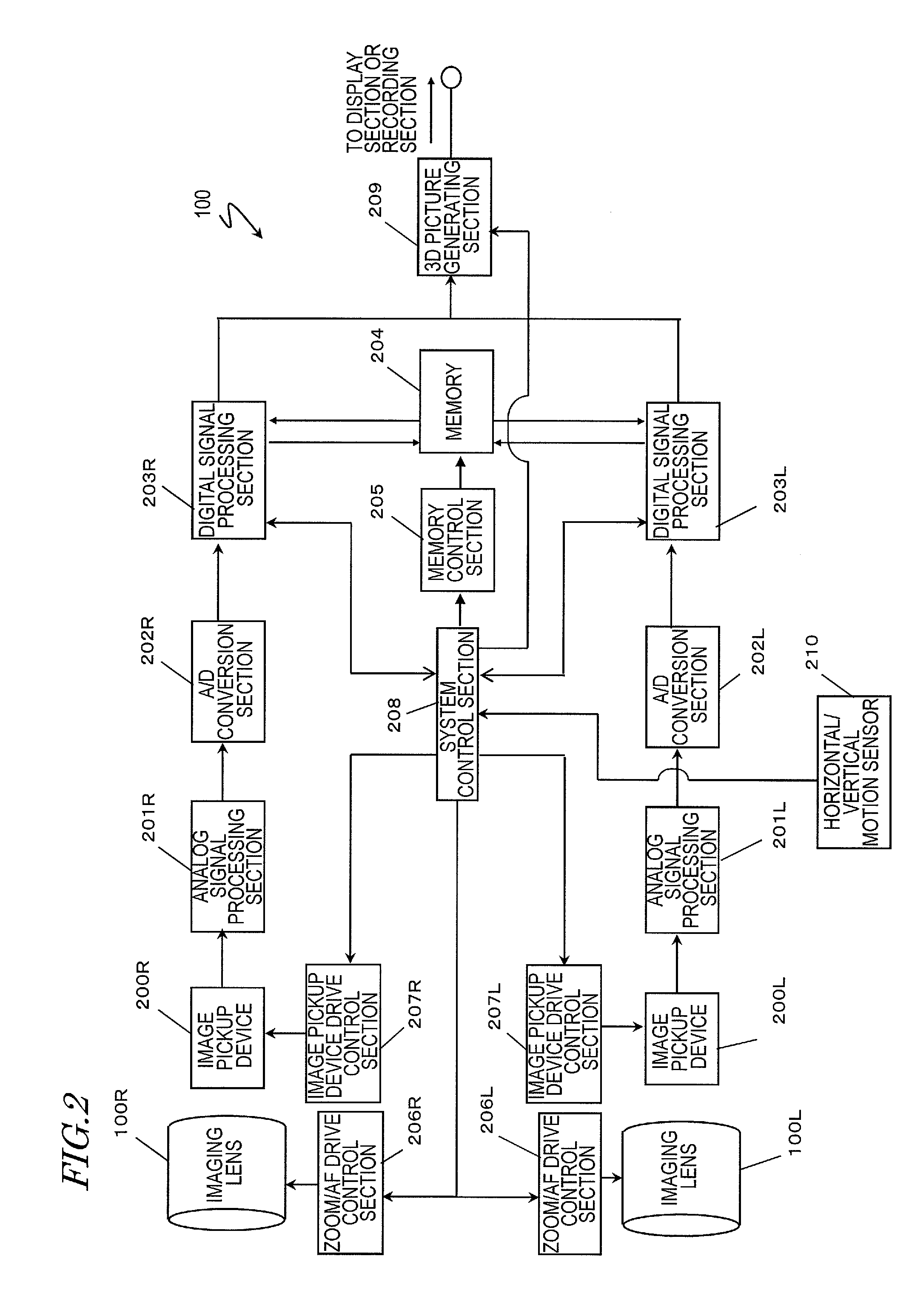
[0087]As a second embodiment of the present invention, an example is described below in which switching is made between 3D imaging and 2D imaging depending on the magnitude of camera shake which occurs when the image pickup apparatus 100 is held in hands during imaging, instead of depending on camera operation such as panning or tilting. The basic structure of the image pickup apparatus 100 in the second embodiment is the same as the one illustrated in FIGS. 1 and 2, and a description thereof is therefore omitted.

[0088]In video imaging with an image pickup apparatus, the blurring of a taken picture due to camera shake is inevitable if the image pickup apparatus is held in hands by a person taking the image during imaging. An example of known technologies for correcting picture blurring due to camera shake during imaging involves detecting a motion vector between consecutive images and cutting out a part of an image based on the motion vector. In another existing correction technolog...

third embodiment

[0104]An image pickup apparatus 200 according to a third embodiment of the present invention is described with reference to FIG. 8 and FIG. 9. The image pickup apparatus 200 is a modification of the image pickup apparatus 100 (FIG. 2) in which a stereo base changing section 800 for varying the physical distance (hereinafter, referred to as stereo base) between the imaging lenses 100R and 100L is added and controlled by a system control section 801. The basic operation of the system control section 801 is the same as that of the system control section 208 (FIG. 2). In the image pickup apparatus 200 of FIG. 8, components that are the same as those in the image pickup apparatus 100 are denoted by the same reference symbols to avoid repeating the same description.

[0105]FIG. 8 is a block diagram illustrating the internal structure of the image pickup apparatus 200 according to the third embodiment of the present invention. The two imaging lenses (optical systems) 100R and 100L are dispos...


PUM


Abstract

An image pickup apparatus capable of taking a 3D picture may produce a 3D picture that gives a viewer a sense of strangeness if panning, tilting, or considerable camera shake occurs during imaging. Provided is an image pickup apparatus including: a motion detecting section, which detects the motion of the image pickup apparatus; and a picture data outputting section, which switches its output between 2D picture data and 3D picture data obtained by picking up subject images, depending on the detected motion of the image pickup apparatus. An appropriate picture is provided by switching the output between 2D picture data and 3D picture data depending on the motion of the image pickup apparatus. An appropriate picture is provided also by changing the stereo base of optical systems, or adjusting a parallax between the left image and the right image, in accordance with the motion of the image pickup apparatus.

Description

BACKGROUND OF THE INVENTION[0001]1. Field of the Invention[0002]The present invention relates to an image pickup apparatus, and more particularly, to an image pickup apparatus having a function of taking a two-dimensional (2D) video and a three-dimensional (3D) video.[0003]2. Description of the Related Art[0004]Some television and movie contents of recent years are provided in a 3D format, and an environment that allows general users easy viewing of 3D pictures is on the way. In conjunction with this, image pickup apparatus manufacturers have proposed cameras capable of taking a 3D picture.[0005]The common conventional method of taking a 3D picture is to photograph the same subject from different view points at the same time and obtain and generate a 3D picture from the amount of parallax between the view points. However, because a 3D picture is seen through a process in which the human brain recognizes a picture formed from parallax images as a three-dimensional image, images seen ...

Claims


Application Information

Patent Timeline
IPC IPC(8): H04N13/02H04N13/239
CPCH04N13/0022H04N13/0239H04N5/23258H04N13/0296H04N13/0289H04N13/289H04N13/296H04N13/239H04N13/128H04N23/681H04N23/6812
Inventor KUSAKA, HIROYA
Owner PANASONIC CORP
Why Eureka
Try Eureka