Measurement system for varus/valgus angles in feet

a measurement system and varus/valgus angle technology, applied in the field of measuring devices for feet, can solve the problems of difficult to maintain proper contact and alignment between the soles of the bicycle, stress on the muscles, bones, tendons and ligaments of the bicyclist's foot (as well as other parts of the body), and difficulty for the rider to maintain proper contact and alignment between the soles, etc., to achieve the effect of a larger (but more accurate) varus/valgus

Inactive Publication Date: 2012-04-05
SMIRMAN MARIE
View PDF5 Cites 8 Cited by
  • Summary
  • Abstract
  • Description
  • Claims
  • Application Information

AI Technical Summary

Benefits of technology

[0016]In accordance with the general teachings of the present invention, a new and improved measurement system is provided for determining the varus and/or valgus angles of a pronating and/or supinating foot, especially when the subtalar joint of the foot is placed and/or maintained in a neutral position. More specifically, the present invention provi

Problems solved by technology

This situation is especially problematic for individuals with existing pronation and/or supination conditions, wherein significant rearfoot and/or forefoot valgus and/or varus conditions are present.
Because of these different mechanical conditions being present, the bicyclist's foot needs to maintain constant and consistent medial-lateral even pressure over the pedals, and without this even pressure, the muscles, bones, tendons and ligaments of the bicyclist's foot (as well as other parts of the body) can become stressed and/or injured as the ankle repeatedly rolls, or attempts to roll, either laterally or medially.
In these situations, it is difficult for the rider to maintain proper contact and alignment betwee

Method used


Image

  • Measurement system for varus/valgus angles in feet
  • Measurement system for varus/valgus angles in feet
  • Measurement system for varus/valgus angles in feet

Examples


Embodiment Construction

[0047]The following description of the preferred embodiment(s) is merely exemplary in nature and is in no way intended to limit the invention, or uses.

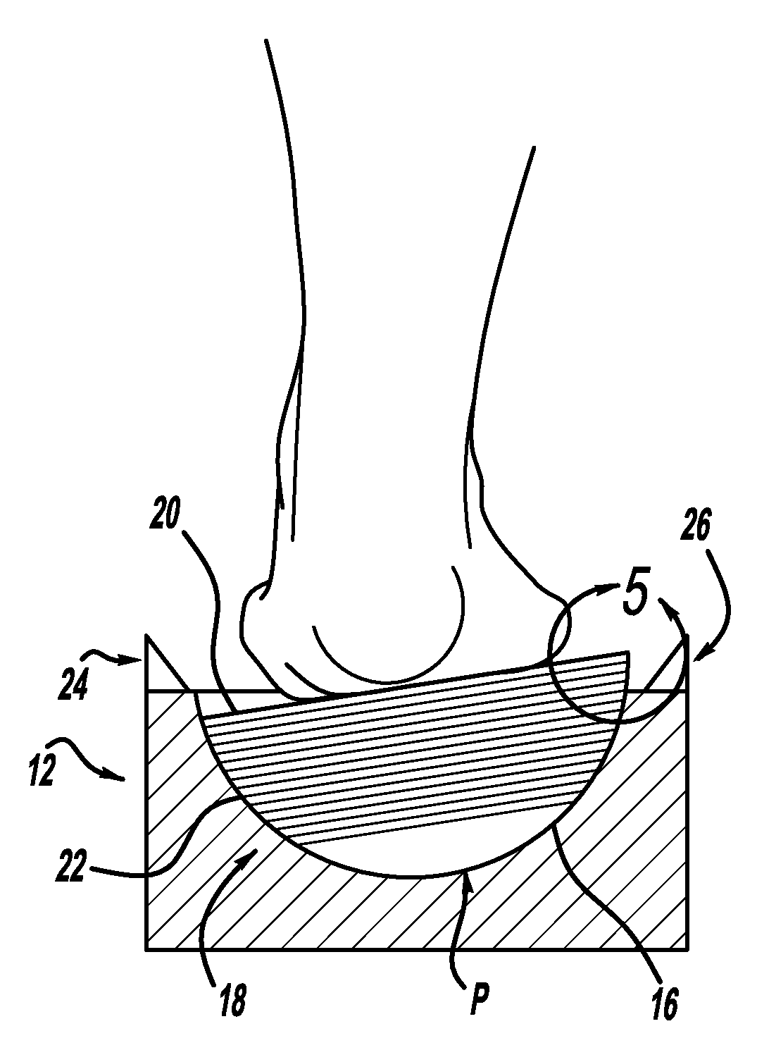
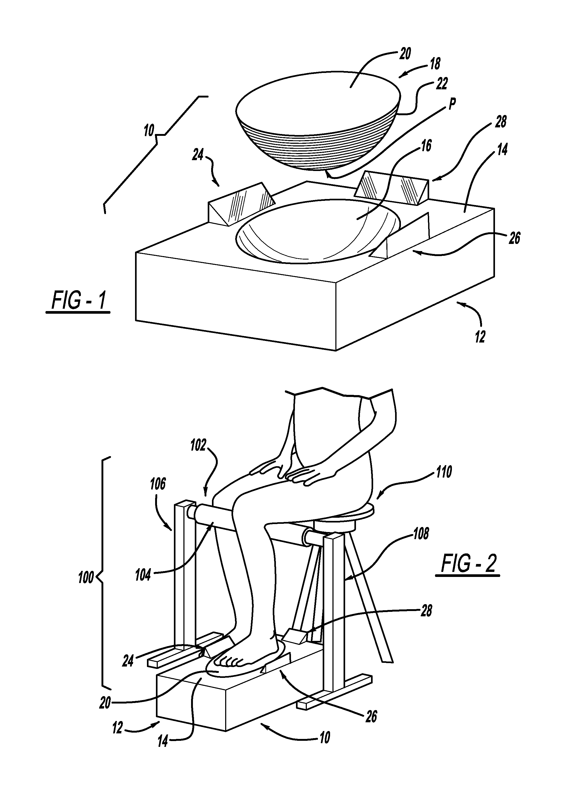
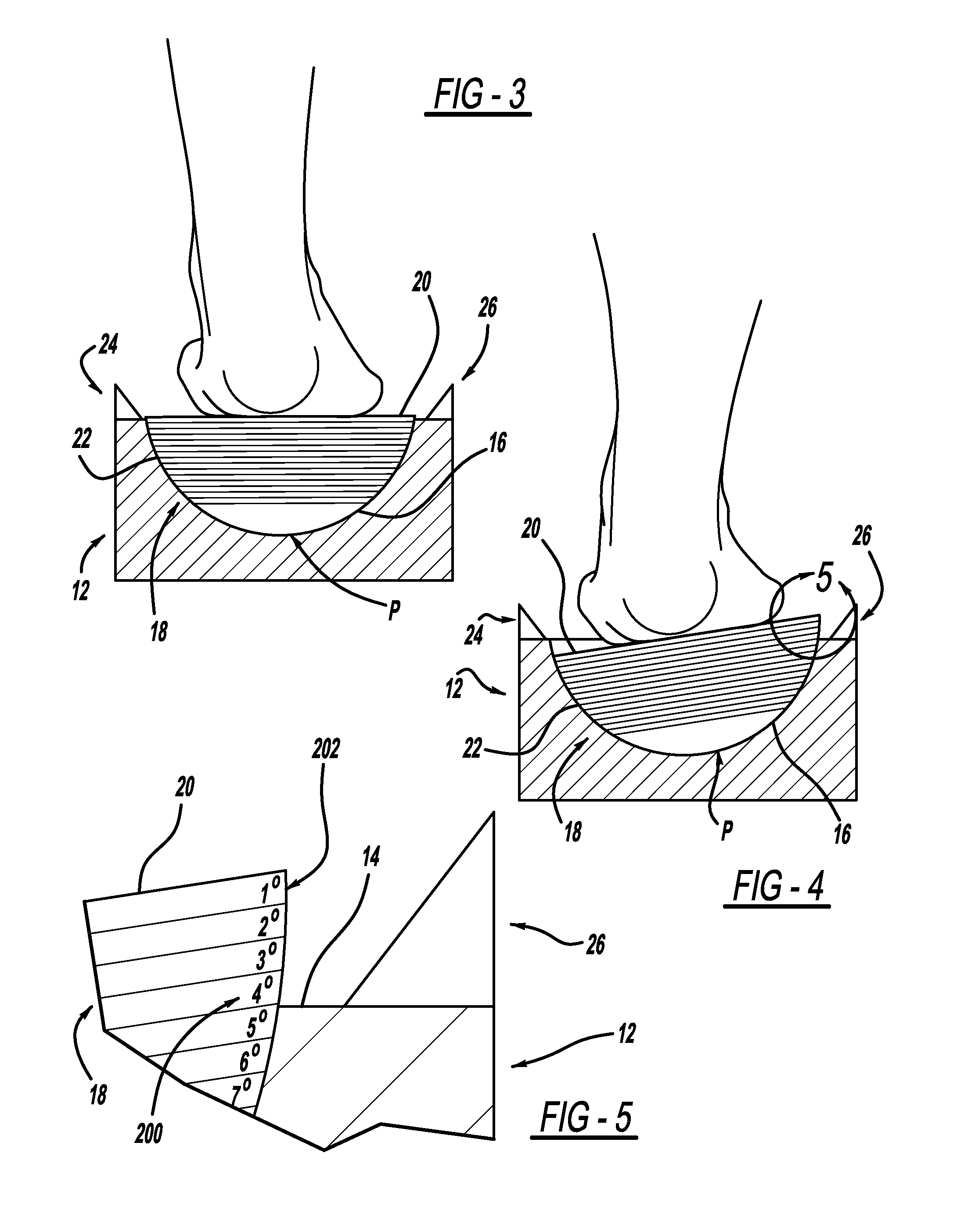
[0048]Referring to FIG. 1, there is shown a measurement system generally at 10 that is selectively operable to determine the varus and / or valgus angles of a pronating and / or supinating foot, especially when the subtalar joint of the foot is placed and / or maintained in a neutral position. The system 10 primarily includes a base portion 12 that can be configured in any number of shapes including, but not limited to squares, rectangles, circles, ovals, and / or the like. On a top surface 14 of the base portion 10 there is provided an area defining a depression 16 formed therein. In this view, the depression 16 is substantially hemispherically shaped. A platform member 18, which includes a substantially planar top surface 20 and a substantially hemispherically shaped bottom surface 22 is intended to interoperate with the depression 16. By w...


PUM


Abstract

A measurement system is described for determining the varus and/or valgus angles of a pronating and/or supinating foot, especially when the subtalar joint of the foot is placed and/or maintained in a neutral position. When the user's foot is maintained in the subtalar joint neutral position, it causes a substantially hemispherically shaped platform member to rotate relative to a correspondingly shaped depression formed in a base portion such that a top surface of the platform member is no longer in a coplanar relationship with a top surface of the base portion. When this occurs, a bottom surface of the platform member is exposed. As a result, indicia are exposed which correspond to degree markings disposed on the bottom surface of the platform member. The degree markings indicate the angle that corresponds to the amount of pronation and/or supination of the user's foot.

Description

CROSS-REFERENCE TO RELATED APPLICATION[0001]The instant application claims priority to U.S. Provisional Patent Application Ser. No. 61 / 388,096, filed Sep. 30, 2010, pending, the entire specification of which is expressly incorporated herein by reference.FIELD OF THE INVENTION[0002]The present invention relates generally to measurement devices for feet and more specifically to a measurement system for determining the varus and / or valgus angles of a pronating and / or supinating foot, with respect to the knee joint axis, when the subtalar joint of the foot is placed and / or maintained in a neutral position.BACKGROUND OF THE INVENTION[0003]Conventional bicycles typically have pedals that are substantially perpendicular to the bike frame, that is, the pedals are parallel to the knee joint axis. However, many individuals have feet that are not parallel to the knee joint axis, especially when the feet are in the subtalar neutral position.[0004]This situation is especially problematic for ind...

Claims


Application Information

Patent Timeline
IPC IPC(8): G01B3/56
CPCA61B5/1121A61B5/0079
Inventor SMIRMAN, MARIE
Owner SMIRMAN MARIE
Why Eureka
Try Eureka