Bidirectional dc-dc converter and control method thereof

a dc-dc converter and bi-directional technology, applied in the direction of dc-dc conversion, power conversion system, dc source parallel operation, etc., can solve the problems of downsizing and efficiency improvement, and achieve the effect of slow body diode reverse recovery characteristics, low switching loss, and fast switching characteristics

Active Publication Date: 2012-04-26
HITACHI INFORMATION & TELECOMM ENG LTD
View PDF7 Cites 18 Cited by
  • Summary
  • Abstract
  • Description
  • Claims
  • Application Information

AI Technical Summary

Benefits of technology

[0009]In general, downsizing and efficiency improvement of a bidirectional DC-DC converter can be effectively accomplished by using a switching device that exhibits fast switching characteristics. However, even when a high-voltage MOSFET is used as the switching device in order to transfer electrical power to and from a high-voltage DC power supply and achieve downsizing and efficiency improvement of the aforementioned previously disclosed bidirectional DC-DC converters, such downsizing and efficiency improvement are obstructed because the body diode reverse recovery characteristics of the MOSFET are slower than the switching characteristics of the MOSFET.
[0010]An object of the present invention is to provide a small-size, high-efficiency, bidirectional DC-DC converter that permits the use of a high-voltage MOSFET or other switching device having fast switching characteristics and relatively slow body diode reverse recovery characteristics, exhibits low switching loss, and reduces the influence of relatively slow body diode reverse recovery characteristics. Another object of the present invention is to provide a method for controlling such a bidirectional DC-DC converter.
[0028]The present invention makes it possible to provide a small-size, high-efficiency, bidirectional DC-DC converter that permits the use of a high-voltage MOSFET or other switching device having fast switching characteristics and relatively slow body diode reverse recovery characteristics, exhibits low switching loss, and reduces the influence of relatively slow body diode reverse recovery characteristics.

Problems solved by technology

However, even when a high-voltage MOSFET is used as the switching device in order to transfer electrical power to and from a high-voltage DC power supply and achieve downsizing and efficiency improvement of the aforementioned previously disclosed bidirectional DC-DC converters, such downsizing and efficiency improvement are obstructed because the body diode reverse recovery characteristics of the MOSFET are slower than the switching characteristics of the MOSFET.

Method used


Image

  • Bidirectional dc-dc converter and control method thereof
  • Bidirectional dc-dc converter and control method thereof
  • Bidirectional dc-dc converter and control method thereof

Examples


first embodiment

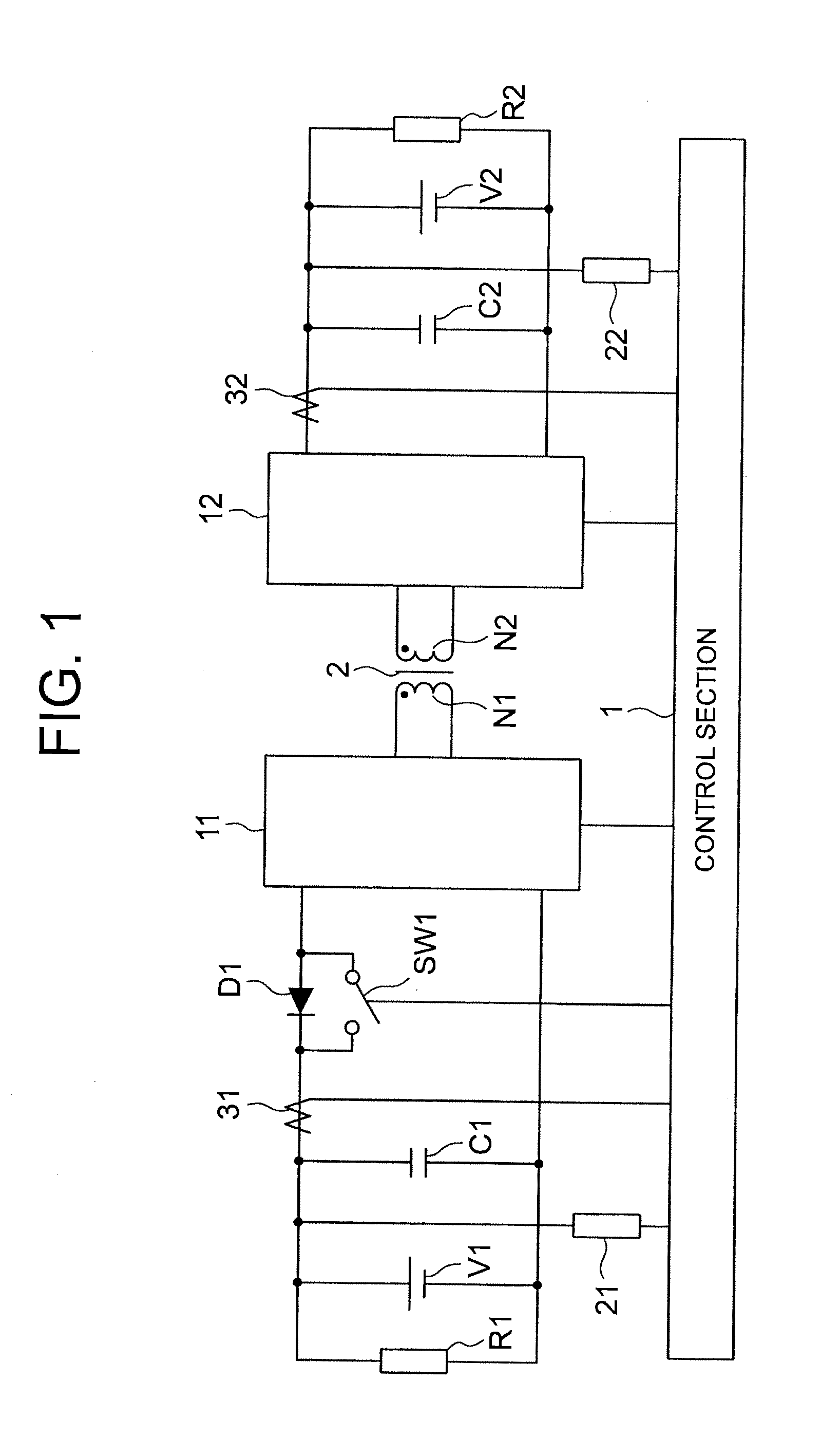
[0037]FIG. 1 is a schematic circuit diagram of a bidirectional DC-DC converter according to a first embodiment of the present invention. The bidirectional DC-DC converter is connected between the DC power supply V1 and the DC power supply V2 to transfer electrical power between the DC power supply V1 and the DC power supply V2. A load R1 is connected to the DC power supply V1, whereas a load R2 is connected to the DC power supply V2.

[0038]Referring to FIG. 1, a smoothing capacitor C1 is connected to the DC power supply V1, whereas a smoothing capacitor C2 is connected to the DC power supply V2. The DC terminals of a switching circuit 11 are connected to the smoothing capacitor C1 through a diode D1. The connection of this diode D1 is oriented so that electrical power flows from the switching circuit 11 to the DC power supply V1 and does not flow from the DC power supply V1 to the switching circuit 11. A switch SW1 is connected in parallel with the diode D1. Further, the DC terminals...

second embodiment

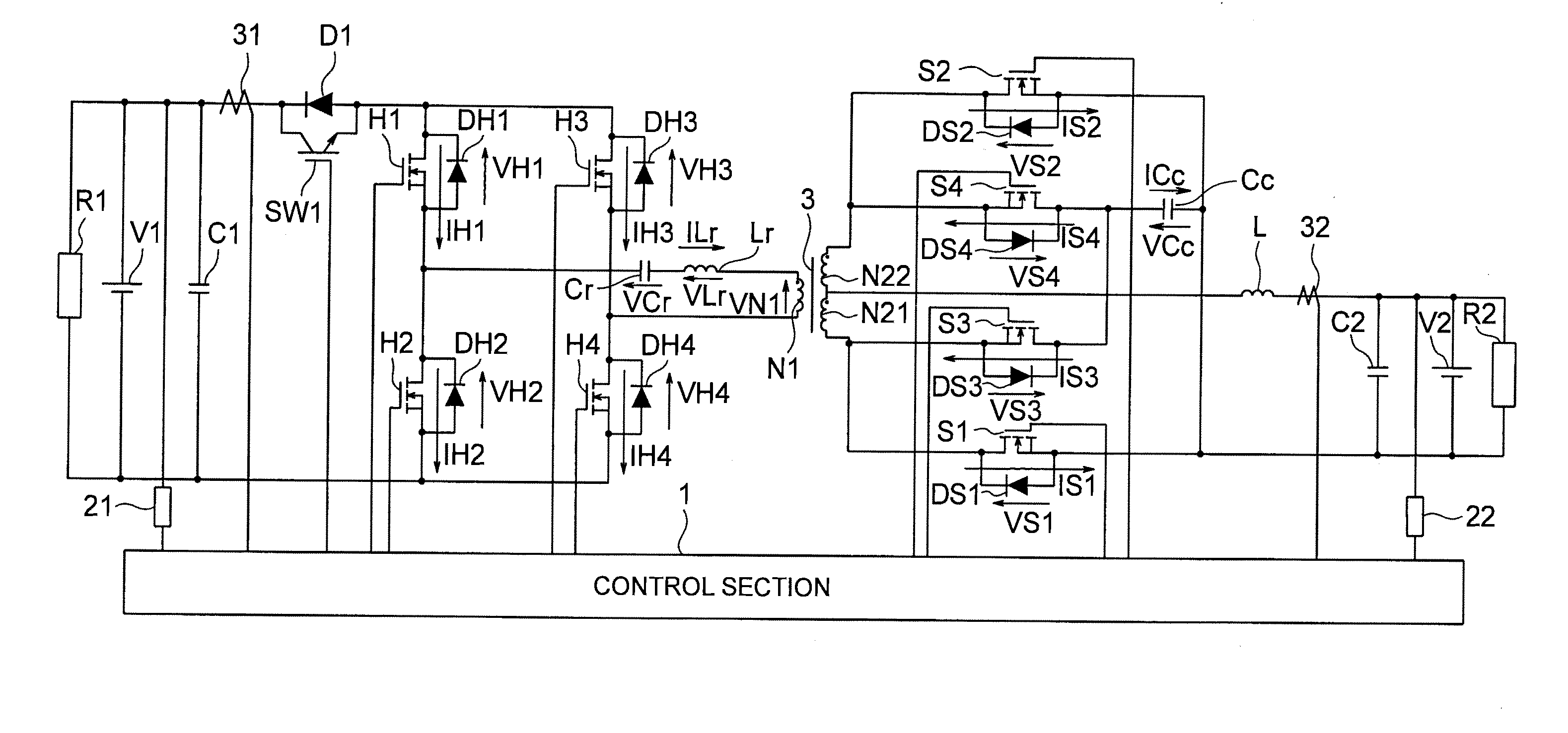
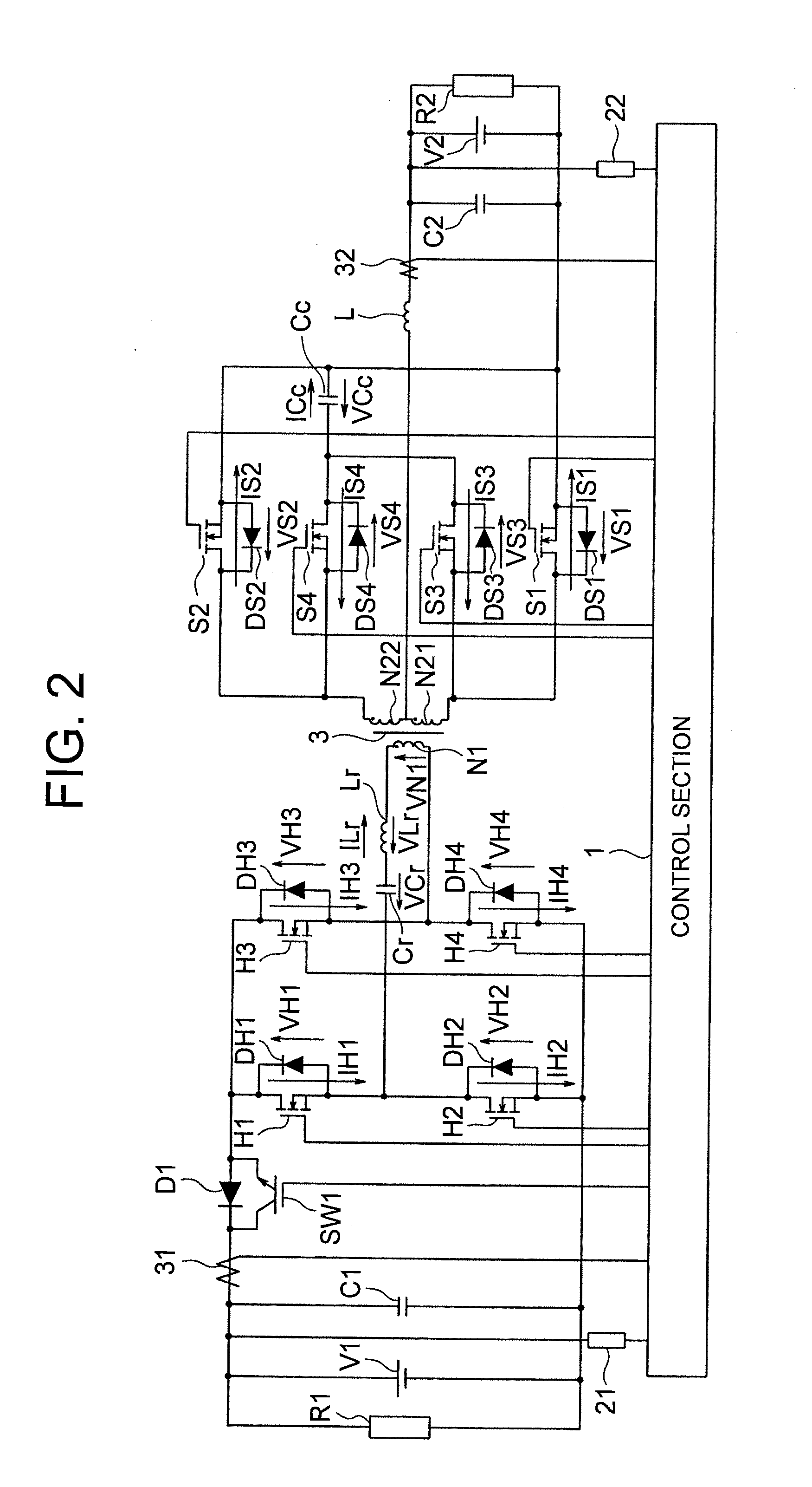
[0048]FIG. 2 is a schematic circuit diagram of a bidirectional DC-DC converter according to a second embodiment of the present invention. The bidirectional DC-DC converter transfers electrical power between a DC power supply V1 and a DC power supply V2, which are connected to opposite ends of the bidirectional DC-DC converter. A load R1 is connected to the DC power supply V1, whereas a load R2 is connected to the DC power supply V2.

[0049]Referring to FIG. 2, a smoothing capacitor C1 is connected to the DC power supply V1, whereas a smoothing capacitor C2 is connected to the DC power supply V2. Switching devices H1, H2 are connected in series with a first switching leg. The first switching leg is connected to the smoothing capacitor C1 through a diode D1. The connection of this diode D1 is oriented so that electrical power flows from the first switching leg to the DC power supply V1 and does not flow from the DC power supply V1 to the first switching leg. A switch SW1 is connected in...

third embodiment

[0107]FIG. 5 is a schematic circuit diagram of a bidirectional DC-DC converter according to a third embodiment of the present invention. The bidirectional DC-DC converter transfers electrical power between a DC power supply V1 and a DC power supply V2, which are connected to opposite ends of the bidirectional DC-DC converter.

[0108]Referring to FIG. 5, a smoothing capacitor C1 is connected to the DC power supply V1, whereas a smoothing capacitor C2 is connected to the DC power supply V2. Switching devices H1 and H2 are connected in series with a first switching leg. The first switching leg is connected to the smoothing capacitor C1 through a diode D1. The connection of this diode D1 is oriented so that electrical power flows from the first switching leg to the DC power supply V1 and does not flow from the DC power supply V1 to the first switching leg. A switch SW1 is connected in parallel with the diode D1. A winding N1, a resonant reactor Lr, and a resonant capacitor Cr are connecte...


PUM


Abstract

Disclosed is a small-size, high-efficiency, isolated, bidirectional DC-DC converter. The bidirectional DC-DC converter includes a transformer in which windings are magnetically coupled, switching circuits, a diode which is connected in parallel with a switch, smoothing capacitors, and a control section. First and second DC power supplies, which are connected in parallel with the smoothing capacitors, respectively, provide bidirectional electrical power transfer. When electrical power is to be transferred from the first DC power supply to the second DC power supply, the switch is maintained in the ON state. When, on the other hand, electrical power is to be transferred from the second DC power supply to the first DC power supply, the switch is maintained in the OFF state to prevent a reverse electrical power flow from the first DC power supply.

Description

CROSS-REFERENCE TO RELATED PATENT APPLICATIONS[0001]Japan Priority Application 2008-224231, filed Sep. 2, 2008 including the specification, drawings, claims and abstract, is incorporated herein by reference in its entirety. This application is a Continuation of U.S. application Ser. No. 12 / 544,107, filed Aug. 19, 2009, incorporated herein by reference in its entirety.BACKGROUND OF THE INVENTION[0002](1) Field of the Invention[0003]The present invention relates to a bidirectional DC-DC converter having an isolation function. The present invention also relates to a method for controlling the bidirectional DC-DC converter.[0004](2) Description of the Related Art[0005]In recent years, increased use of highly efficient hybrid vehicles is promoted due to a rising demand for global environment conservation. The hybrid vehicles have a main battery for driving a traction motor and an auxiliary battery for driving accessories. The degree of freedom in designing a vehicle power supply system c...

Claims


Application Information

Patent Timeline
Patent Type & Authority Applications(United States)
IPC IPC(8): H02J1/10
CPCH02M3/33584H02M3/33507H02M3/28
Inventor SHIMADA, TAKAETANIGUCHI, KIMIAKISHOJI, HIROYUKI
Owner HITACHI INFORMATION & TELECOMM ENG LTD
Why Eureka
Try Eureka