Universal solar illuminator system

a solar energy and solar energy technology, applied in the field of universal solar energy illuminator system, can solve the problems of unsightly (and sometimes dangerous) electrical cords or other connection means, inability to adequately display flags and the like at night, and provide a convenient source of electrical power. , to achieve the effect of enabling and disabling the application of power

Inactive Publication Date: 2012-05-10
WERNER JOEY D +1
View PDF24 Cites 31 Cited by
  • Summary
  • Abstract
  • Description
  • Claims
  • Application Information

AI Technical Summary

Benefits of technology

[0035]Also connected to the circuit board as an incoming power source is a battery pack. The battery pack provides for an independent source of power, and can apply the power to the electrical lines associated with the LED lights through the circuit board. The universal solar illuminator system can also include one or more solar panels which can be positioned in a longitudinal configuration along the universal solar illuminator. As with the battery pack, the solar panels can include electrical conductors running from the solar panels to the circuit board. The electrical conductors essentially conduct electrical power collected by the solar panels, and can transmit the same to the battery pack through the electrical lines associated with the battery pack and the circuit board. The conductors and other circuit elements on the circuit board can not only direct electrical energy collected from the solar panels to the battery pack, but also direct power from the battery pack to the LED lights. Conventional switching elements can also be provided on the circuit board f

Problems solved by technology

However, one difficulty associated with any type of lighting application, particularly with respect to those involving outdoor use, is to provide for a convenient source of electrical power.
That is, outdoor lighting displays are often located a substantial distance away from any conventional sources of commercial power.
Also, connecting lighting displays to remote sources of power can involve unsightly (and sometimes dangerous) electrical cords or other connection means.
However, such flags and the like cannot be adequately displayed at night because of poor visibility.
Also, floodlights are often expensive to purchase, expensive to operate on a daily basis, and difficult to use and maintain.
This provides unsatisfactory visibility for the flag, and adds to the not-insignificant problem of atmospheric light pollution.
Although such a device allows for the use of less light than is required by a floodlight, the device still does not solve the problem of

Method used


Image

  • Universal solar illuminator system
  • Universal solar illuminator system
  • Universal solar illuminator system

Examples


Embodiment Construction

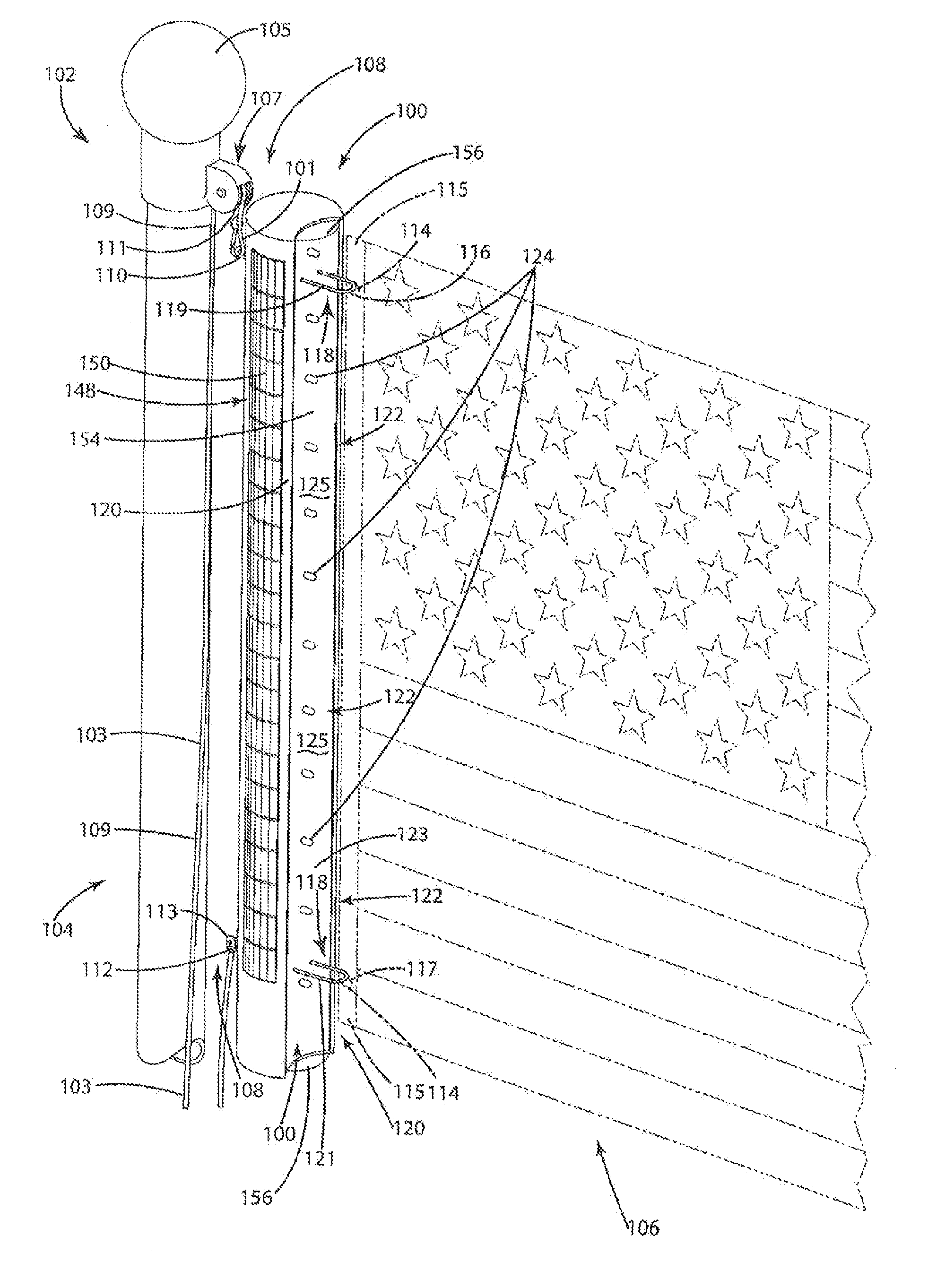
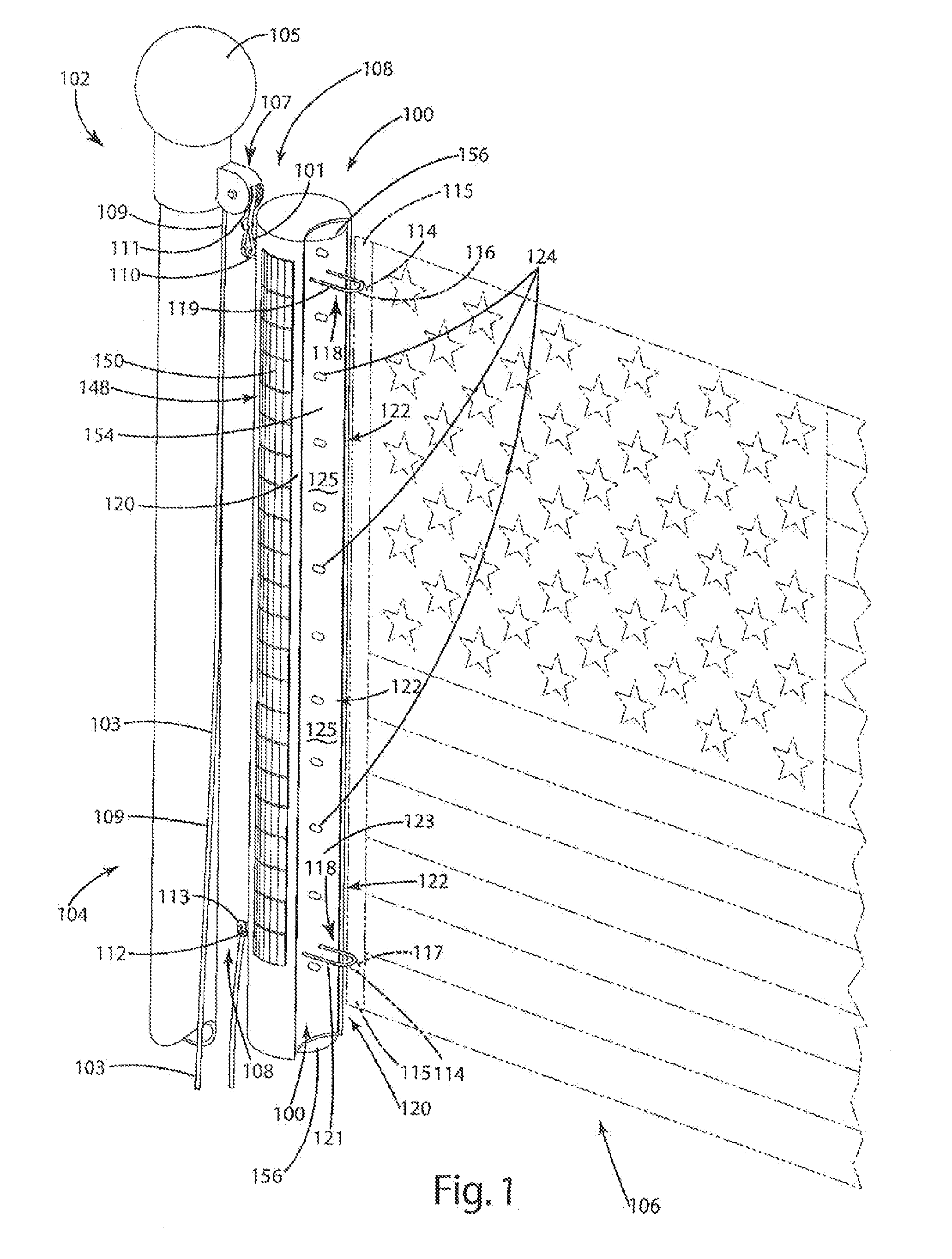
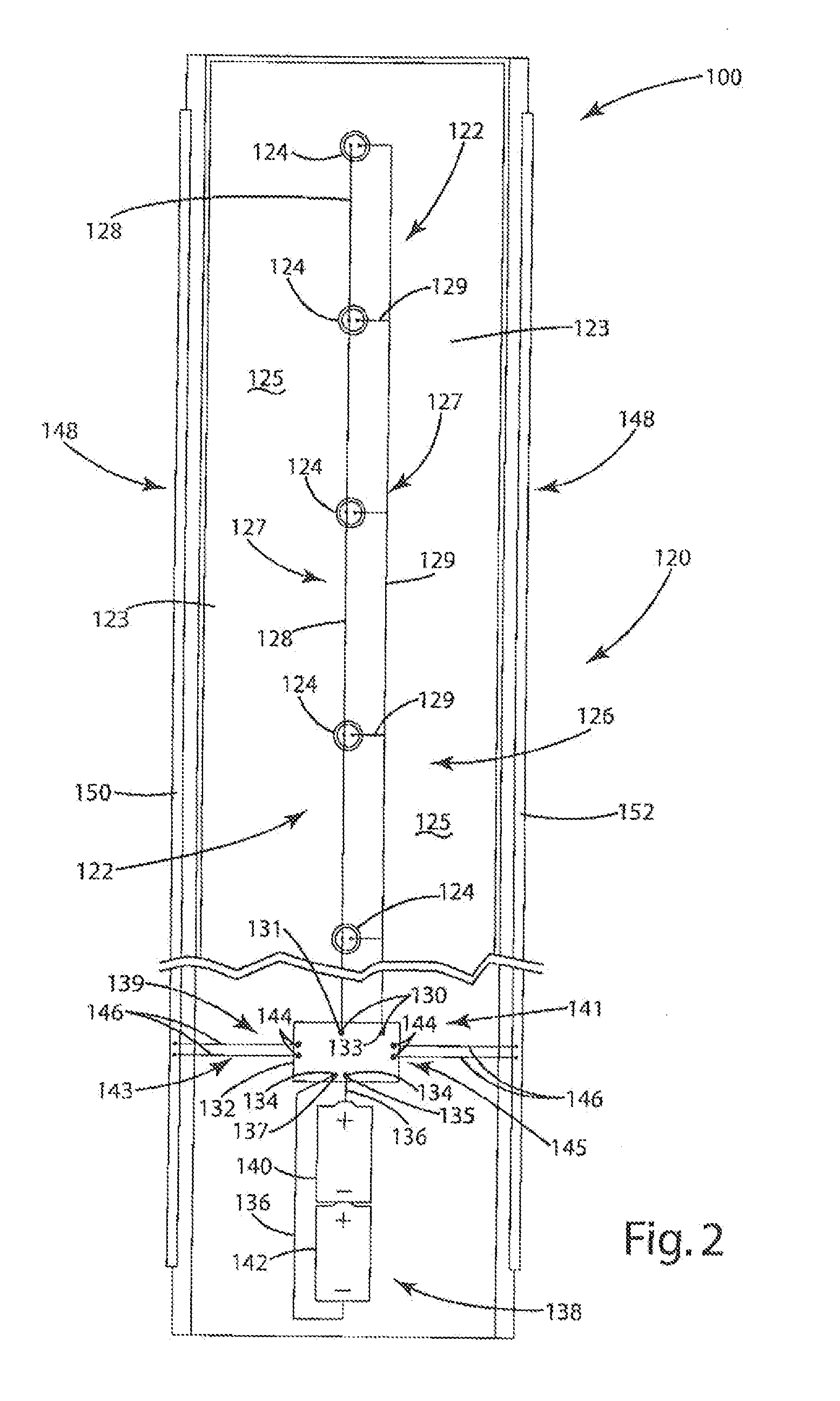
[0045]The principles of the invention are disclosed, by way of example, in embodiments of universal solar illuminator systems as illustrated in FIGS. 1-6, including universal solar illuminator system 100 disclosed herein and illustrated in FIGS. 1-3. As will be made apparent from the description herein, the universal solar illuminator system 100 and other embodiments described herein operate as standalone devices, and may be adapted for selectively illuminating a flag or a banner as desired by the user. The universal solar illuminator systems can be adapted so as to be retrofitted to any existing flagpole apparatus, independent of whether the pole of the flagpole is positioned in a vertical, horizontal or angular orientation.

[0046]Turning specifically to FIGS. 1-3, the universal solar illuminator system 100 is illustrated as being adapted for use with a flagpole apparatus 102. The flagpole apparatus 102 can be conventional in structure and can be any of numerous types of flagpole ap...


PUM


Abstract

A universal solar illuminator system (100) is mounted to a flagpole apparatus (102) having a flagpole (104) and flag (106). The illuminator system (100) includes an elongated structure (120) opening outwardly and exposing a recessed area (123) having a rear, curved surface (125). The system (100) also includes an LED network (126) having a series of LED's (124) energized through a DC circuit (127) from a series battery pack (138). Solar panels (150, 152) charge the series battery pack (138) during daylight conditions.

Description

CROSS-REFERENCE TO RELATED APPLICATIONS[0001]This application is based on and claims priority of U.S. Provisional Patent Application Ser. No. 61 / 410,529 filed Nov. 5, 2010.STATEMENT REGARDING FEDERALLY SPONSORED RESEARCH OR DEVELOPMENT[0002]Not applicable.PARTIES TO A JOINT RESEARCH AGREEMENT[0003]Not applicable.REFERENCE TO A SEQUENCE LISTING[0004]Not applicable.BACKGROUND OF THE INVENTION[0005]1. Field of the Invention[0006]The invention relates to means for producing lighting effects as powered by solar apparatus and, more particularly, lighting effects which may be adapted for use with displays of flags or other banners.[0007]2. Background Art[0008]Ever since the advent of electrical lighting apparatus, a substantial amount of development has been undertaken for achieving new applications for use of lighting effects in various environmental conditions and applications. These applications have involved both functional use of electric light (e.g. street lamps, stop lights and gene...

Claims


Application Information

Patent Timeline
IPC IPC(8): F21L4/08
CPCF21L4/08F21S9/035F21Y2101/02F21S9/037F21W2131/10F21K9/20F21Y2103/10F21Y2115/10Y02B20/72F21L4/02
Inventor WERNER, JOEY D.JOHNSON, WILLIAM L.
Owner WERNER JOEY D
Why Eureka
Try Eureka