Body armor ballistic plate carrier

a plate carrier and body armor technology, applied in the field of plate carriers, can solve the problems of the rear plate not being able to ride high enough on the wearer's back to provide adequate thoracic protection, the position and height of the rear plate on the wearer's back, and the plate carrier not being able to meet the individual wearer's proper fit, etc., to achieve better ballistic coverage of the upper thoracic area and improve thoracic protection

Inactive Publication Date: 2012-05-31
SEUK JO WON
View PDF6 Cites 31 Cited by
  • Summary
  • Abstract
  • Description
  • Claims
  • Application Information

AI Technical Summary

Benefits of technology

[0004]The present invention provides a plate carrier that includes both front and rear panel sections with internal pockets for supporting armor plates and inserts, but positions the rear panel section to provide improved thoracic protection. The front and rear panel sections are suspended by shoulder straps, which connect to the rear panel section at a mid point below the top edge of the rear panel section. The mid point connection of the shoulder straps causes the rear panel section to ride higher than the front panel section and higher on the wearer's back thereby positioning the armor plate inside high on the wearer's back and

Problems solved by technology

Consequently, conventional plate carriers have suffered from issues relating to the proper fit of the plate carrier to the individual wearer.
One common issue with conventional plate carriers is the position and height of the rear plate on the wearer's back.
Because the front and back panels are suspended from shoulder straps

Method used


Image

  • Body armor ballistic plate carrier
  • Body armor ballistic plate carrier
  • Body armor ballistic plate carrier

Examples


Embodiment Construction

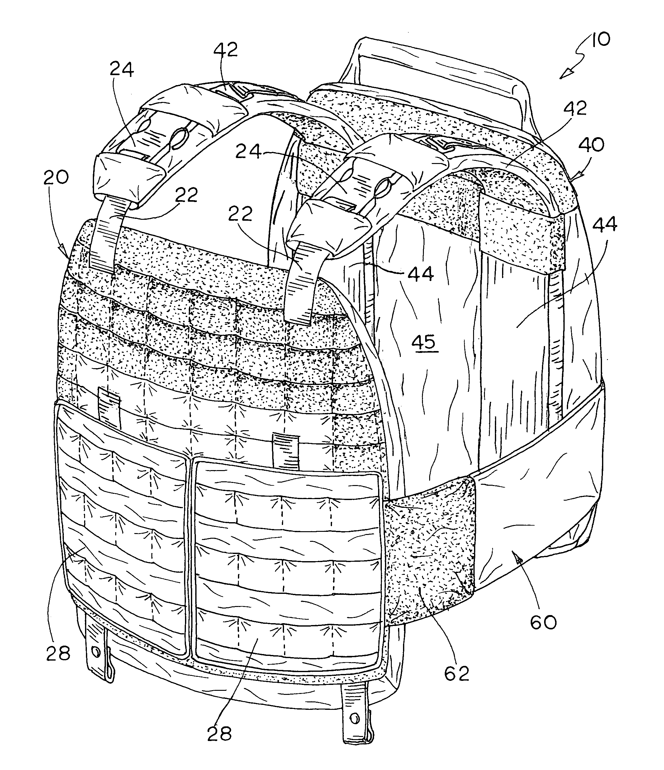
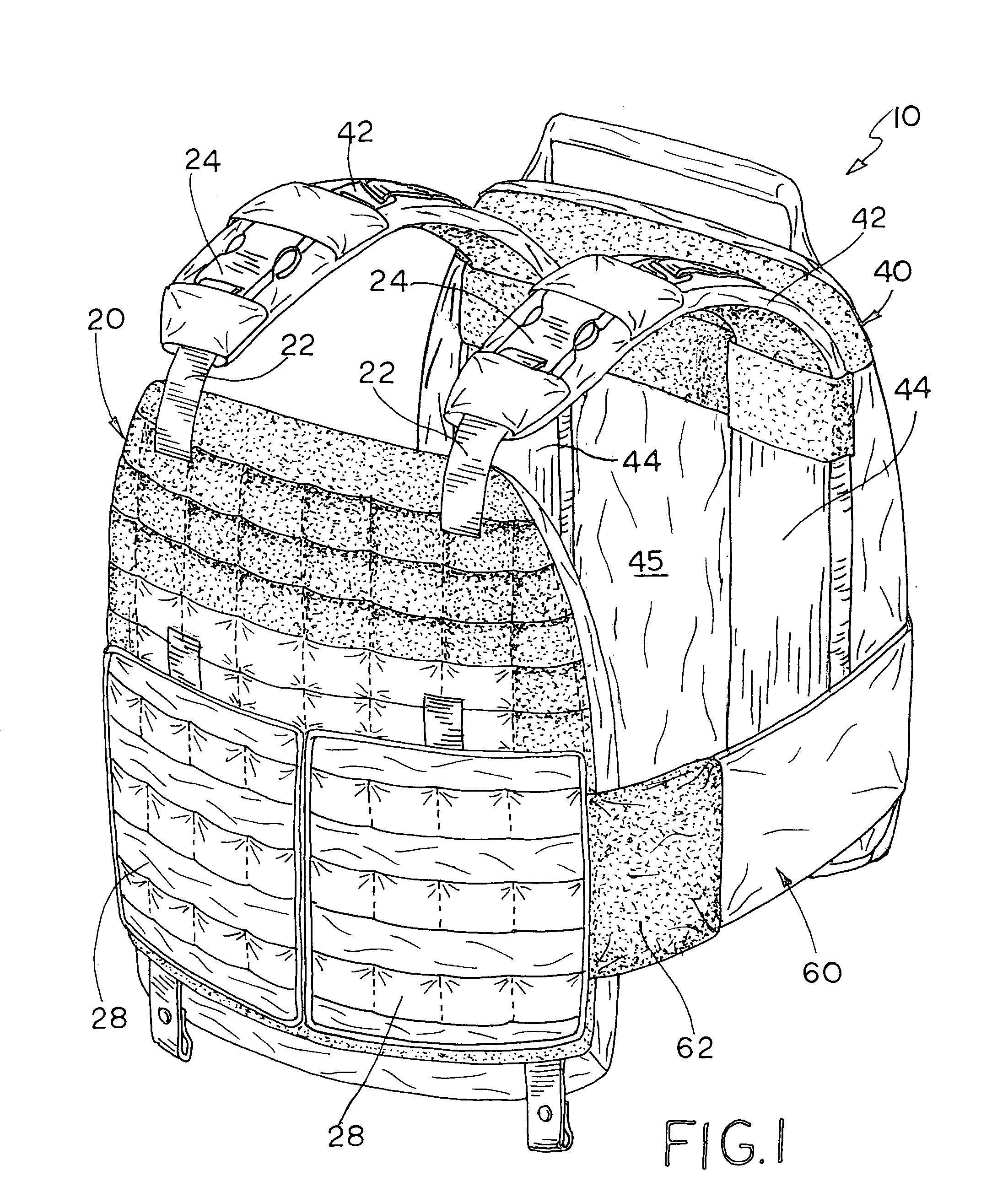
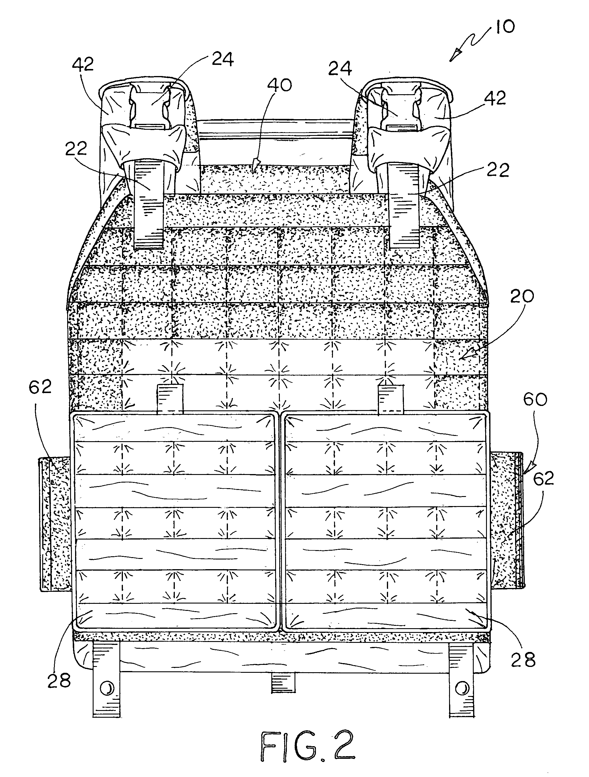
[0023]Referring now to the drawings, FIGS. 1-11 illustrate an embodiment of the plate carrier of the present invention, which is designated generally as reference numeral 10. Plate carrier 10 includes a front panel section 20, a rear panel section 40 and a detachable cummerbund 60. The materials and manner of construction of plate carrier 10 are readily known in the art and will not be described in detail herein; however, plate carrier 10 is sewn and constructed generally of nylon fabrics, such as Cordura® from INVISTA, but can be made from any natural or synthetic cloth or fabric, which resists tears, abrasions and scuffs. The weight of the fabric for the pouch body is selected to provide sufficient rigidity to support the ballistic armor plates and inserts but also any external equipment that may be affixed to the plate carrier. Straps of elastic and nylon webbing are also used in the construction of plate carrier 10 for various components and feature. Hook and loop fasteners, suc...


PUM


Abstract

The present plate carrier includes front and rear panel sections with internal pockets for supporting ballistic plates and inserts, but positions the rear panel section to provide improved thoracic protection. The front and rear panel sections are suspended by shoulder straps, which connect to the rear panel section at a mid point below the top edge of the rear panel section. The mid point connection of the shoulder straps causes the rear panel section to ride higher than the front panel section and higher on the wearer's back thereby positioning the ballistic plate inside high on the wearer's back and providing better ballistic coverage of the wearer's upper thoracic area. One of the internal pockets of each panel section has facing strips of hook and loop material sewn around its inner periphery that adhere together around a ballistic plate to center and hold the plate in place within the pocket. The plate carrier has removable side plate pockets mounted to a detachable cummerbund by hook and loop fasteners allowing the ballistic plates to be properly positioned on the cummerbund.

Description

[0001]This is a continuation-in-part of pending U.S. patent application Ser. No. 12 / 927,975 filed on Nov. 30, 2010.[0002]This invention relates to ballistic resistant “body armor” and in particular, a plate carrier for rigid ballistic plates and flexible ballistic inserts.BACKGROUND AND SUMMARY OF THE INVENTION[0003]Body armor and particularly “plate carriers” are well known in the military and law enforcement communities. Plate carriers are garments that support rigid ballistic armor plates and / or flexible ballistic armor inserts within internal pockets or pouches of the carrier. The plate carrier is generally comprised of front and back panel sections connected by shoulder straps and a waist strap or cummerbund. Generally, conventional plate carriers are not sized and proportioned for particular wearers but to accommodate the sizes of inserts and armor plates, which are typically available in small, medium, large and extra large sizes. Consequently, conventional plate carriers hav...

Claims


Application Information

Patent Timeline
IPC IPC(8): F41H5/08
CPCF41H1/02
Inventor SEUK, JO WON
Owner SEUK JO WON
Why Eureka
Try Eureka