
Mechanical finger

a technology of mechanical fingers and fingers, applied in the field of mechanical fingers, can solve problems such as impracticality of mechanical fingers

Active Publication Date: 2012-07-19
KINOVA INC
View PDF11 Cites 3 Cited by
  • Summary
  • Abstract
  • Description
  • Claims
  • Application Information

AI Technical Summary

Benefits of technology

[0006]Therefore, in accordance with a first embodiment, there is provided a mechanical finger comprising: at least two phalanges, with the at least two phalanges having tubular bodies and being made of a semi-rigid material, one of the at least two phalanges being a base phalange adapted to be secured to a base; another of the at least two phalanges being an end phalange, the end phalange being pivotally connected to an adjacent one of the a...

Problems solved by technology

In domestic applications, such a mechanical finger may be impractical, especially in an environment with relatively fragile objects.

Method used


Image

  • Mechanical finger
  • Mechanical finger
  • Mechanical finger

Examples


Embodiment Construction

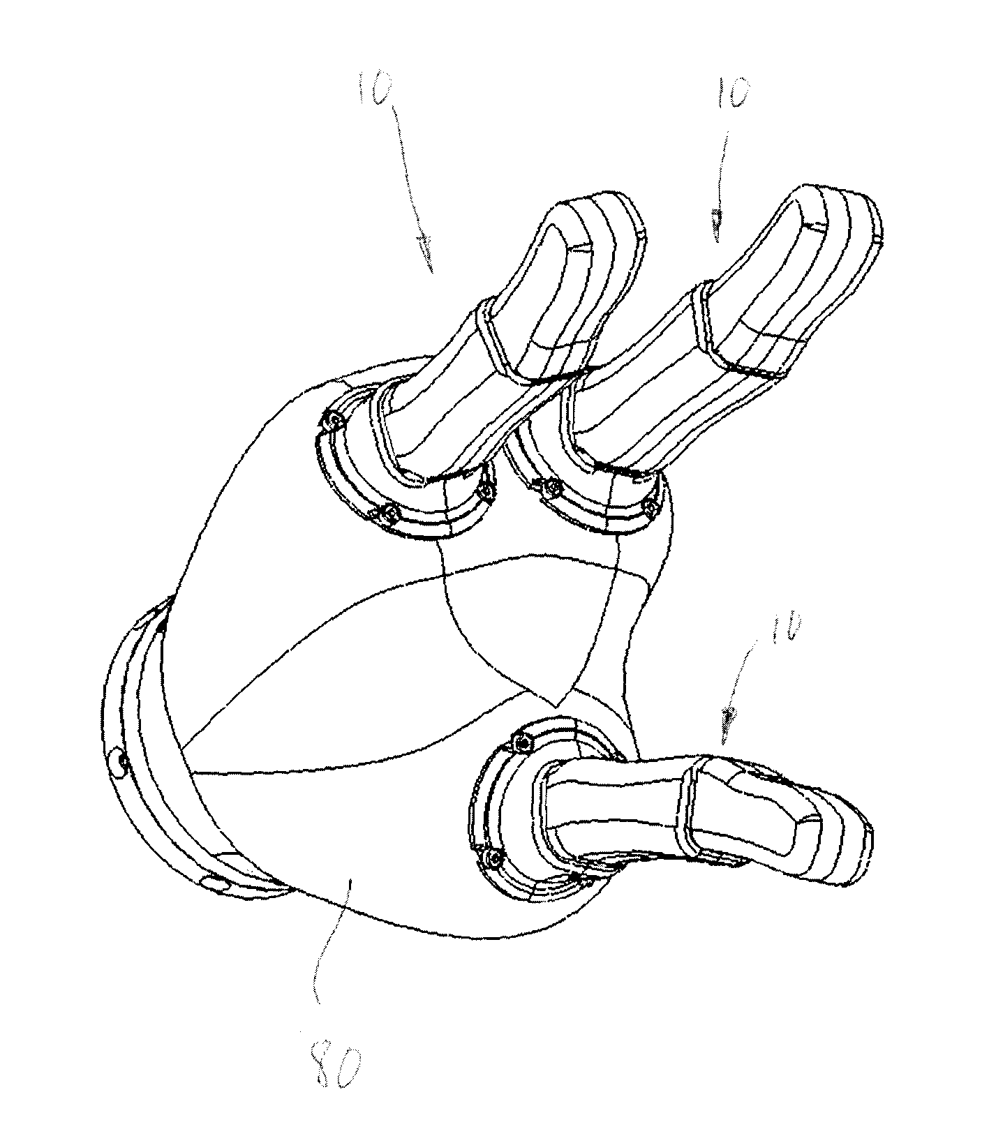
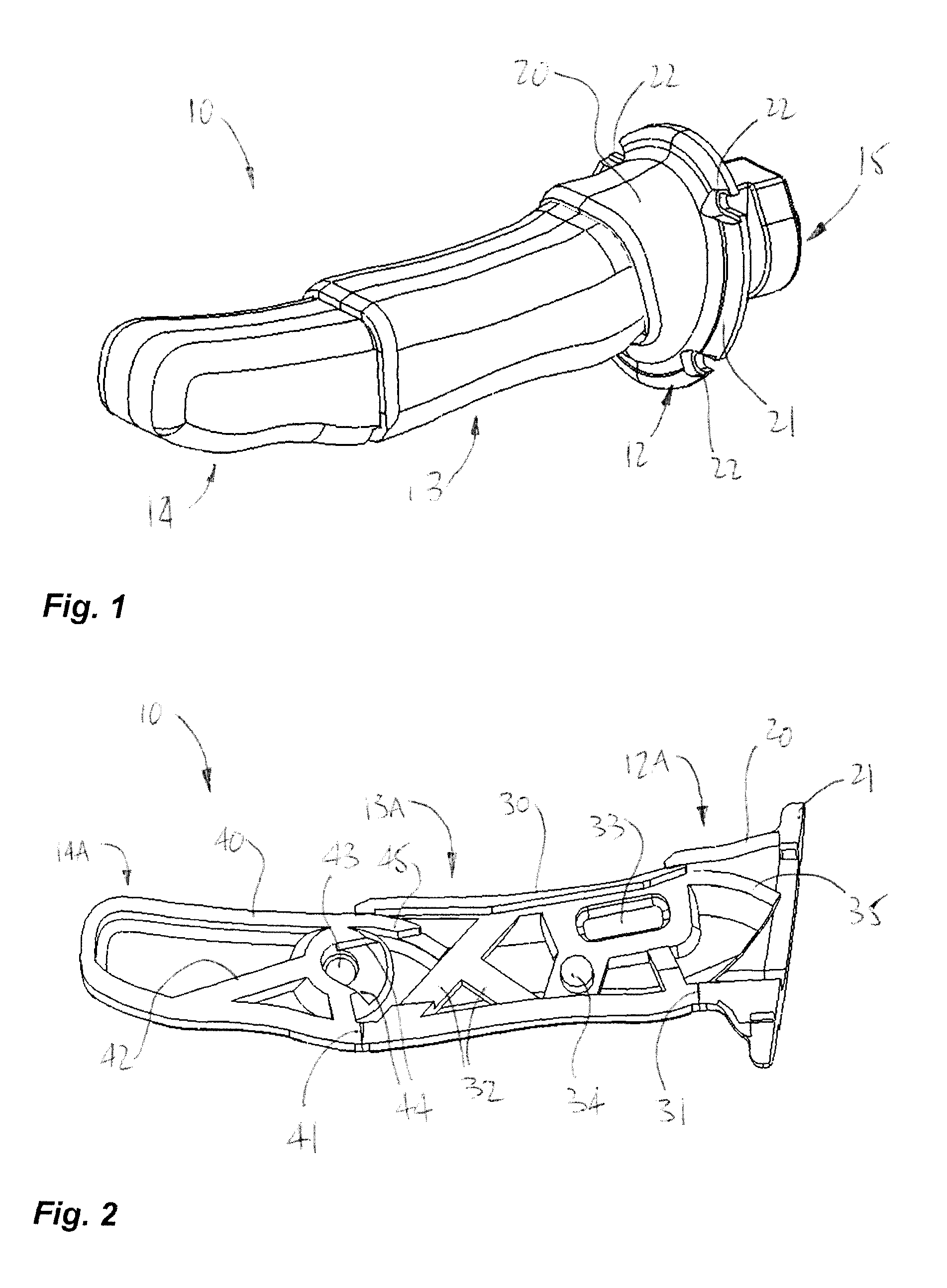
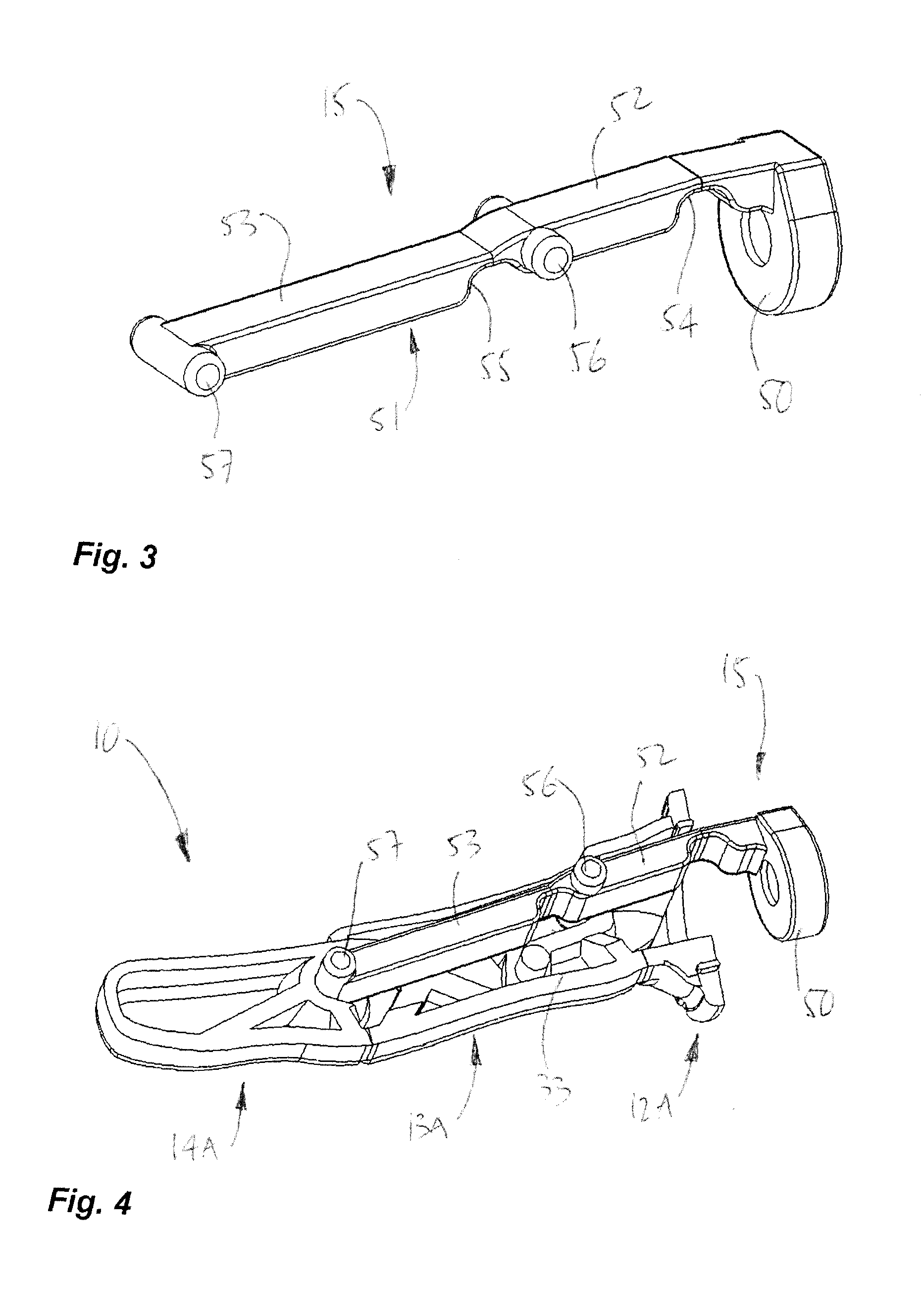
[0036]Referring to the drawings, and more particularly to FIG. 1, a mechanical finger constructed in accordance with an embodiment is generally shown at 10. The finger 10 has a base phalange 12, a middle phalange 13 and an end phalange 14, although more or fewer than three phalanges may be used in the mechanical finger of the present disclosure. The three-phalange configuration illustrated in FIG. 1 is however well suited to simulate a human finger, whereby the present disclosure will focus on the three-phalange configuration. Movements of the mechanical finger 10 are performed by actuation of a skeleton member 15.

[0037]Referring concurrently to FIGS. 1 and 2, the phalanges 12-14 of the mechanical finger 10 each consist in a pair of shells made of a semi-rigid material, such as rubber, as will be described hereinafter. In FIG. 2, half-phalanges are shown as 12A, 13A and 14A (i.e., first shells), with the plane of separation being parallel to a longitudinal axis of the finger 10. The...


PUM


Abstract

A mechanical finger comprises at least two phalanges. The phalanges have tubular bodies made of a semi-rigid material. One phalange is adapted to be secured to a base. Another phalange is connected to an adjacent phalange for pivoting movement with respect to the adjacent phalange. A skeleton member in the tubular bodies of the phalanges moves to actuate the pivoting motion of the phalanges with respect to one another. The skeleton member is connected to a degree of actuation to cause the pivoting motion of the phalanges with respect to one another. An assembly is also provided. The assembly comprises at least two of the mechanical finger, a palm actuator comprising a base for connection of the base phalange of each mechanical finger, and at least one degree of actuation connected to the skeleton member. The degree of actuation causes a grasping movement of the mechanical fingers.

Description

CROSS-REFERENCE TO RELATED APPLICATION(S)[0001]The present application claims priority on U.S. Patent Application No. 61 / 186,497, filed Jun. 12, 2010, and on U.S. Patent Application No. 61 / 227,511, filed Jul. 22, 2009, and incorporated herein by reference.FIELD OF THE APPLICATION[0002]The present application relates to mechanical fingers and more particularly to mechanical fingers used in prosthesis applications and in technical-aid applications, amongst numerous possible applications.BACKGROUND OF THE ART[0003]Mechanical fingers of all types have been developed as a function of various applications. One common type of mechanical finger has phalanges in an articulated configuration, to simulate the human finger. In such configurations, the articulated phalanges are displaced with respect to one another to grasp objects of all shapes. For instance, U.S. Pat. No. 5,762,390, by Gosselin et al., describes a mechanical finger performing motions similar to that of the human finger. Accord...

Claims


Application Information

Patent Timeline
IPC IPC(8): A61F2/54
CPCA61F2/586A61F2/588Y10S901/39B25J15/0009B25J9/0009
Inventor CARON L'ECUYER, LOUIS JOSEPHDEQUIRE, CHARLES
Owner KINOVA INC
Learn More