Spreader spring

a technology of springs and spreaders, which is applied in the field of brake systems, can solve the problems of springs not being used with existing braking systems, spreader springs may not be added to this braking system, and each brake pad is more expensive and time-consuming to produce, so as to reduce drag in the brake assembly, minimize movement and/or eliminate the effect of movemen

Inactive Publication Date: 2012-07-26
AKEBONO BRAKE
View PDF3 Cites 14 Cited by
  • Summary
  • Abstract
  • Description
  • Claims
  • Application Information

AI Technical Summary

Benefits of technology

[0012]Another possible method of using the present invention includes reducing drag in a brake assembly comprising; compressing a brake spring; and placing the brake spring between ends of a pair of brake pads; wherein the brake spring includes: a first arm with at least two arcuate portions, a second arm with at least two arcuate portions, a body portion between and connected to the first arm and the second arm; and a contact point at the end of first arm and the second arm that contact the pair of brake pads; wherein the contact points each contact a different brake pad and assist in moving the brake pads in the retract direction.
[0013]One unique aspect of the present invention envisions a spreader spring that can be incorporated into existing braking systems without the need for any modifications to the braking system, additional parts, adding expense, labor, or a combination thereof to the braking systems. The present invention does not require any additional holes and / or coupling areas in which contact with the pressure plates of the brake pads is made so that the spreader spring may assist in retracting the brake pads, thus, the present invention may be used with a significant number of existing brake pad designs. Further, the present invention fits outside of the caliper housing and extends laterally away from the caliper housing and brake rotor so that the spreader spring may be used regardless of the caliper housing employed by the braking system.
[0014]Another unique aspect of the present invention envisions a spreader spring that may be used with a significant number of pad clips and or braking systems. The spreader spring may be incorporated around portions of and / or into portions of the pad clips so that vertical displacement (e.g., movement perpendicular to the face of the support bracket) of the spreader spring is minimized. The spreader spring may further extend through and / or around portions of the pad clip so that a portion of the spreader spring is in close proximity to and / or in contact with the support bracket so that movement is minimized and / or eliminated.
[0015]Still another unique aspect of the present invention assists in retraction of the brake pads and maximizes air gap of the disk brake system. The present invention maximizes the air gap between the brake pads and the rotor, which minimizes or even eliminates unwanted contact of the rotor and brake pads during non-braking vehicle operation and, thus, minimizes or eliminates DVT growth without creating a long petal travel or causing the brake pads to feel soft to the user. By minimizing DVT growth the present invention further prevents noise, vibration, & harshness issues from developing. Therefore, the present inventor has identified that the present invention may be employed in existing braking systems so that the present invention will improve brake pad life, rotor life, and fuel efficiency due to reduced brake drag.

Problems solved by technology

In addition these springs may not be used with existing braking systems because the spring does not fit without the modifications discussed above.
One problem faced by these springs is that they work with “new” brake designs, or brakes modified specifically for each design.
Another problem faced by known springs is that they require holes to be drilled in the pressure plate of a brake pad, which makes each brake pad more expensive and time consuming to produce.
Thus, a spreader spring may not be added to this braking system without adding a brake pad with a specific design.
Yet another problem of know springs is that some of the springs are “over the rotor” designs (i.e. the spring is placed directly over the rotor) and are subject to interference with moving parts such as the rotor or the wheel.
For example, the spreader spring may contact the rotor, the caliper housing, or both and move out of contact with the brake pads, become damaged, or become tangled within other parts causing damage to the other parts such as the rotor, brake pads, fluid lines, tires, or a combination thereof.
The over the rotor designs may require additional clips and / or support structures so that the spring does not contact other parts of the braking system, thus, adding expense to the brake system and preventing the spreader spring from being added to existing systems easily.
Another such problem faced by known disk brake systems is lateral run out (LRO) and disk thickness variation (DTV).

Method used


Image

  • Spreader spring
  • Spreader spring
  • Spreader spring

Examples


Embodiment Construction

[0024]The following description of the preferred embodiment(s) is merely exemplary in nature and is in no way intended to limit the invention, its application, or uses.

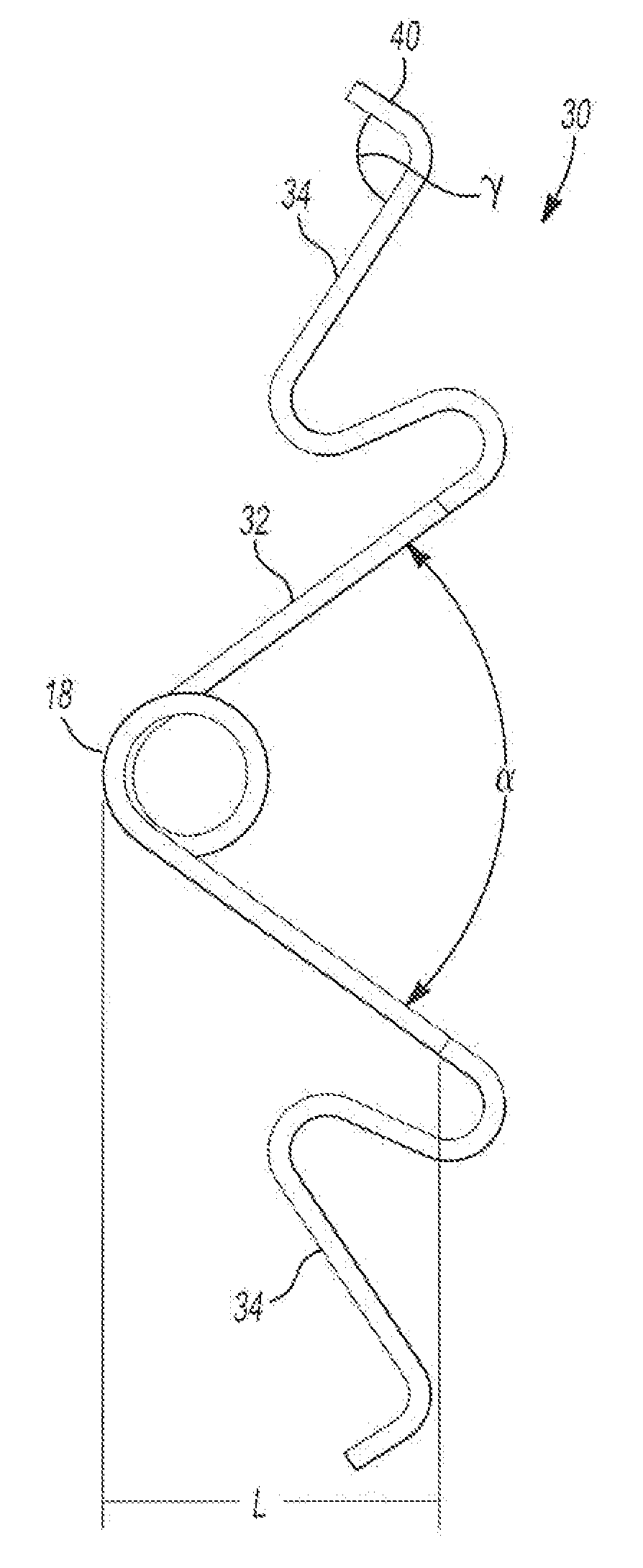
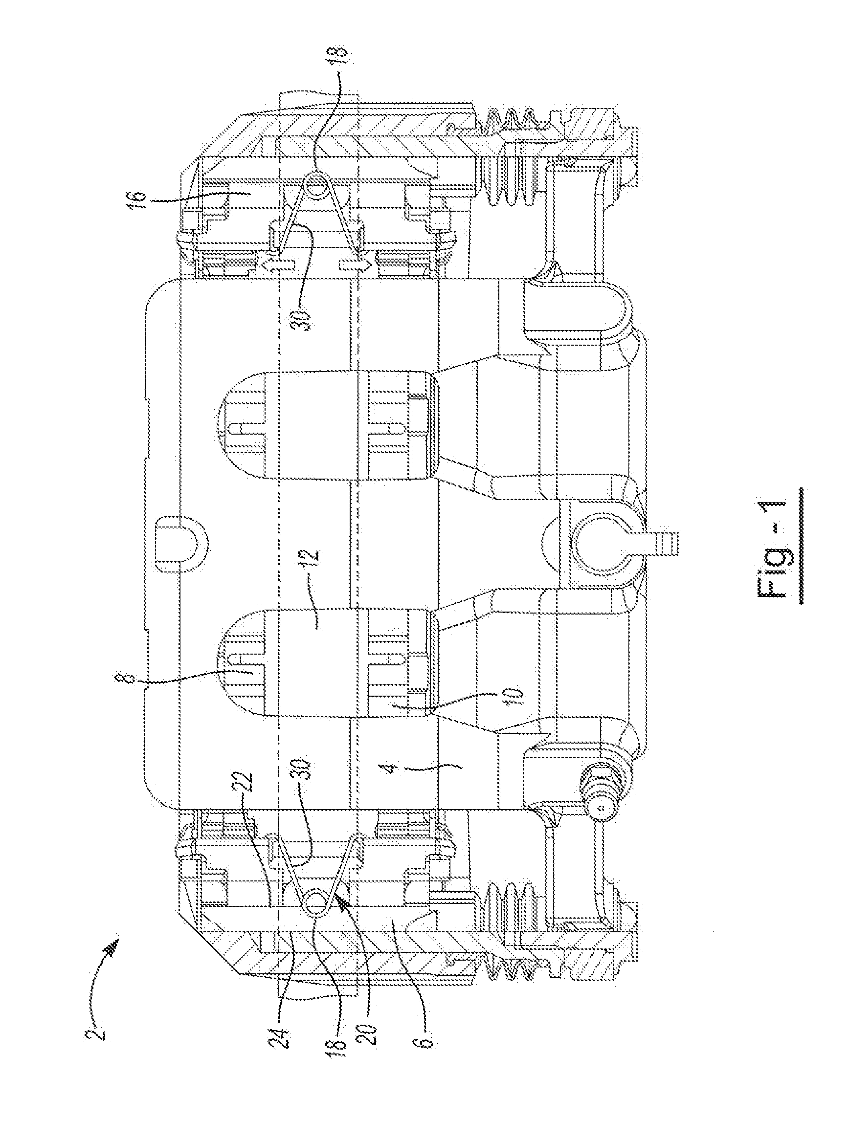
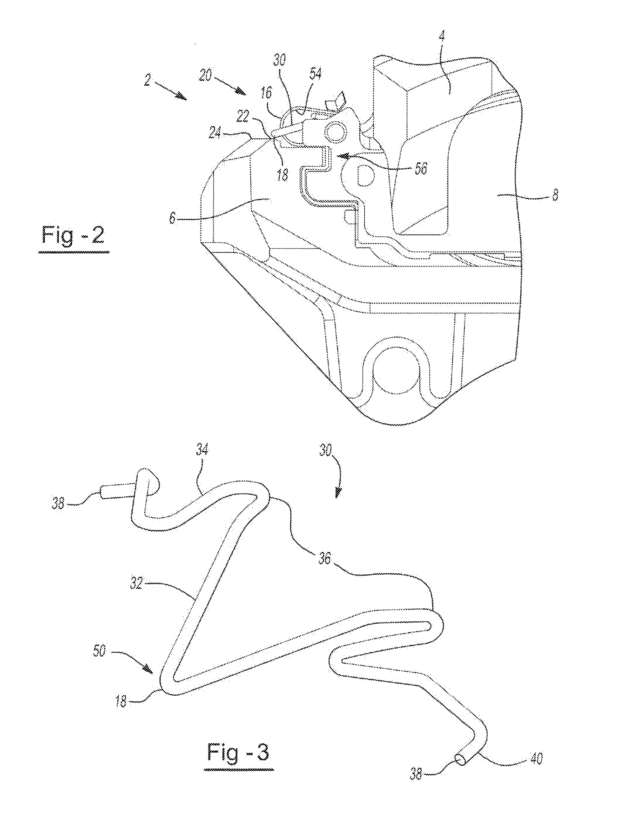
[0025]The present invention is predicated upon providing an improved spreader spring for use with a brake assembly in vehicles. For example, the spreader spring may be used with almost any brake assembly and the brake assembly may be used with almost any vehicle (e.g. car, truck, bus, train, airplane, or the like). Alternatively, the spreader spring and brake assembly may be integrated into components used for manufacturing or other equipment that require a brake such as a lathe, winder for paper products or cloth, amusement park rides, or the like. However, the present invention is most suitable for use with a passenger vehicle (i.e. a car, truck, sports utility vehicle, or the like).

[0026]Generally, a disc brake assembly includes a caliper body, a rotor, and two brake pads. The caliper body is in communication with ...


PUM

PropertyMeasurementUnit
angleaaaaaaaaaa
angleaaaaaaaaaa
angleaaaaaaaaaa

Abstract

A brake assembly comprising: at least one brake spring that includes: a first arm; a second arm, the first arm and the second arm forming a first arm plane; and a body portion between and connecting to the first arm and the second arm, the body portion forming a body plane, the body plane being at an angle relative to the first arm plane; wherein the at least one brake spring is between and in communication with a pressure plate of at least two brake pads.

Description

FIELD OF THE INVENTION[0001]The present invention generally relates to a brake system and more particularly a spreader spring that assists in retracting brake pads.BACKGROUND OF THE INVENTION[0002]Typical, disc brake systems include a support bracket, two more brake pads, a caliper, and a rotor. The at least two brake pads are mounted and located adjacent to the support bracket so that the brake pads move axially towards and away from the rotor. The disc brake system may include a pad clip that attaches to the support bracket and to a portion of the one or more brake pads so that the brake pads are held in the support bracket. The disc brake system may include one or more springs that attach to the brake pads to assist in retracting the brake pads. The addition of one or more clips and / or one or more springs may require modifications to be made to the support bracket, brake pads, caliper body, or a combination thereof so that the spring and / or pad clip may be used. In addition these...

Claims


Application Information

Patent Timeline
Patent Type & Authority Applications(United States)
IPC IPC(8): F16D55/22B23P17/04F16D65/095
CPCF16D65/0972Y10T29/49908F16D65/0977F16D65/0975
Inventor GUTELIUS, KENNETH ERIC
Owner AKEBONO BRAKE
Why Eureka
Try Eureka