Non-pneumatic wheel assembly with removable hub

a technology of non-pneumatic wheels and hubs, which is applied in the direction of high-resiliency wheels, vehicle components, and spoked wheels, etc., can solve the problems that the integration of hubs and web spokes may not be practical or undesirabl

Active Publication Date: 2012-08-16
MICHELIN RECH & TECH SA +1
View PDF9 Cites 56 Cited by
  • Summary
  • Abstract
  • Description
  • Claims
  • Application Information

AI Technical Summary

Benefits of technology

[0011]In each of the exemplary embodiments set forth above, the hub is removably attached. This feature allows for replacement of other portions of the wheel assembly. In addition, because t

Problems solved by technology

In such case, integral attachment of the hub and the web

Method used


Image

  • Non-pneumatic wheel assembly with removable hub
  • Non-pneumatic wheel assembly with removable hub
  • Non-pneumatic wheel assembly with removable hub

Examples


Embodiment Construction

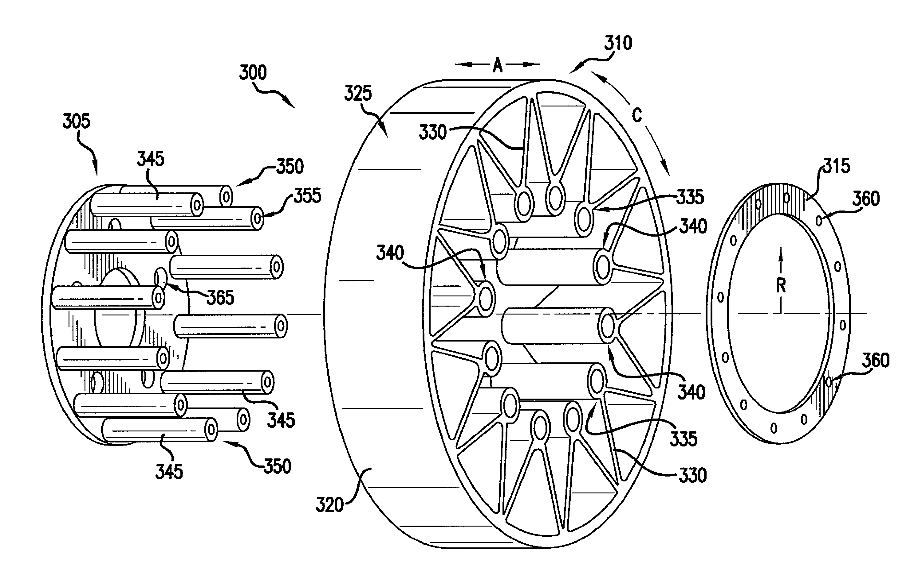
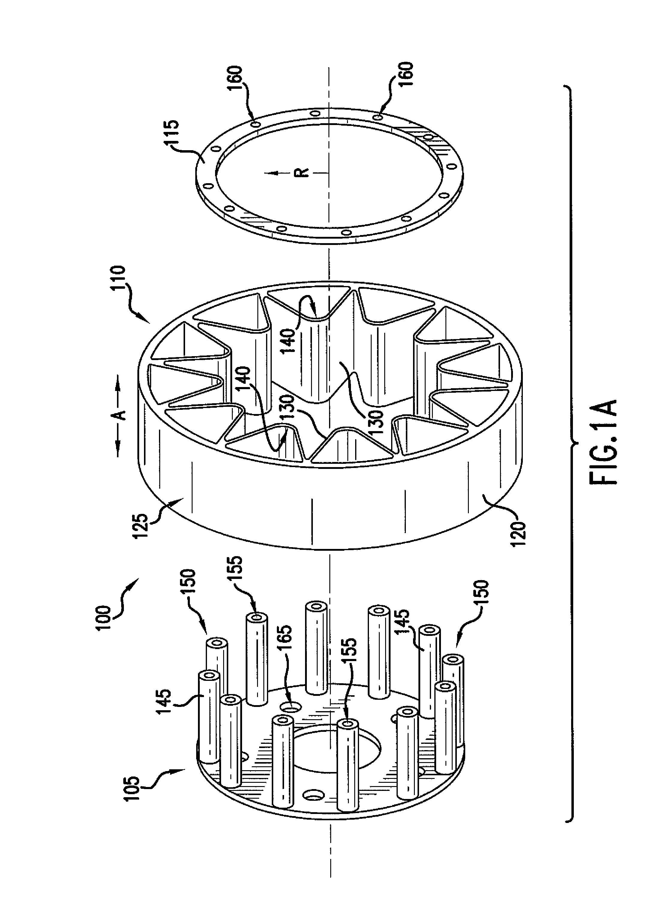
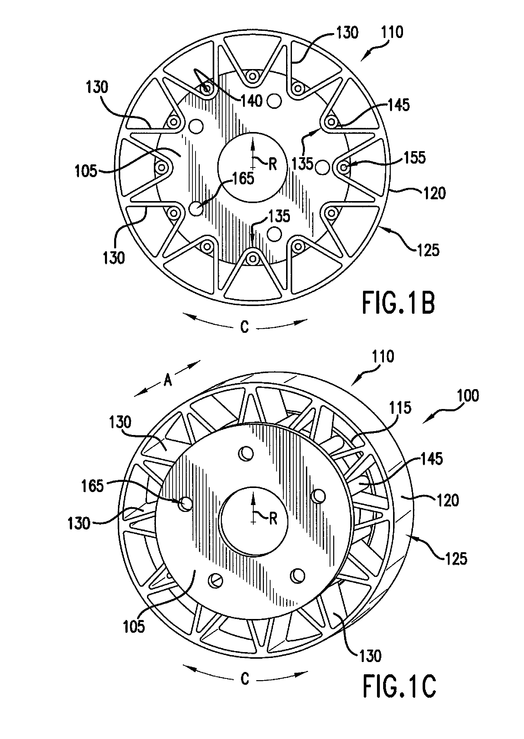
[0018]The present invention relates to a non-pneumatic wheel and, more particularly, to a non-pneumatic wheel having a removable hub attachment whereby the hub may be reused and the remaining portion of the non-pneumatic wheel replaced as needed. For purposes of describing the invention, reference now will be made in detail to embodiments of the invention, one or more examples of which are illustrated in the drawings. Each example is provided by way of explanation of the invention, not limitation of the invention. In fact, it will be apparent to those skilled in the art that various modifications and variations can be made in the present invention without departing from the scope or spirit of the invention. For instance, features illustrated or described as part of one embodiment, can be used with another embodiment to yield a still further embodiment. Thus, it is intended that the present invention covers such modifications and variations as come within the scope of the appended cl...


PUM


Abstract

A non-pneumatic wheel assembly is provided. More particularly, a non-pneumatic wheel assembly is provided having a removable hub i.e., a hub that may be separated from the remainder of the wheel assembly. The hub may be reused and other portions of the non-pneumatic wheel assembly replaced as needed. In addition, the hub may be constructed from a different material than used for other portions of the non-pneumatic wheel.

Description

FIELD OF THE INVENTION[0001]The present invention relates to a non-pneumatic wheel assembly and, more particularly, to a non-pneumatic wheel assembly having a removable hub whereby the hub may be reused and the non-pneumatic wheel replaced as needed.BACKGROUND OF THE INVENTION[0002]Non-pneumatic tires and wheels have been disclosed. By way of example, U.S. Pat. No. 7,201,194, which is incorporated herein by reference, describes a non-pneumatic tire. In an exemplary embodiment, this non-pneumatic tire includes an outer annular shear band and a plurality of web spokes that extend transversely across and radially inward from the annular band and are connected to a hub. In certain exemplary embodiments, the annular shear band may further comprise a shear layer, at least a first membrane adhered to the radially inward extent of the shear layer and at least a second membrane adhered to the radially outward extent of the shear layer. Under load, the annular band deforms in the contact area...

Claims


Application Information

Patent Timeline
IPC IPC(8): B60B9/04
CPCB60B1/0223B60B21/06B60B1/042B60B1/0261B60B1/0276B60B9/04B60B9/14
Inventor ENDICOTT, JAMES
Owner MICHELIN RECH & TECH SA
Why Eureka
Try Eureka