Resonance enhanced rotary drilling

Active Publication Date: 2012-09-27
ITI SCOTLAND
View PDF2 Cites 18 Cited by
  • Summary
  • Abstract
  • Description
  • Claims
  • Application Information

AI Technical Summary

Benefits of technology

[0022]According to a third aspect of the present invention there is provided a resonance enhanced rotary drill which is suitable for use with the previously described control apparatus and method. The resonance enhanced rotary drill comprises: a rotary drill bit; and an oscillator for applying axial oscillatory loading to the rotary drill bit, wherein the oscillator comprises a piezoelectric actuator with mechanic amplification, a magnetostrictive actuator, a pneumatic actuator, or an electrically driven mechanical actuator. The p

Problems solved by technology

Accordingly, although U.S. Pat. No. 3,990,522 discusses the possibility of resonance, it would appear that the low frequencies attainable by its oscillator are insufficient to achieve resonance enhanced drilling through many hard materials.
Regardless of the frequency issue discussed above, resonance cannot easily be achieved and maintained in any case using the arrangement of U.S. Pat. No. 3,990,522, particularly if the drill passes through different materials having different resonance characteristics.
As such, it is difficu

Method used


Image

  • Resonance enhanced rotary drilling
  • Resonance enhanced rotary drilling
  • Resonance enhanced rotary drilling

Examples


Embodiment Construction

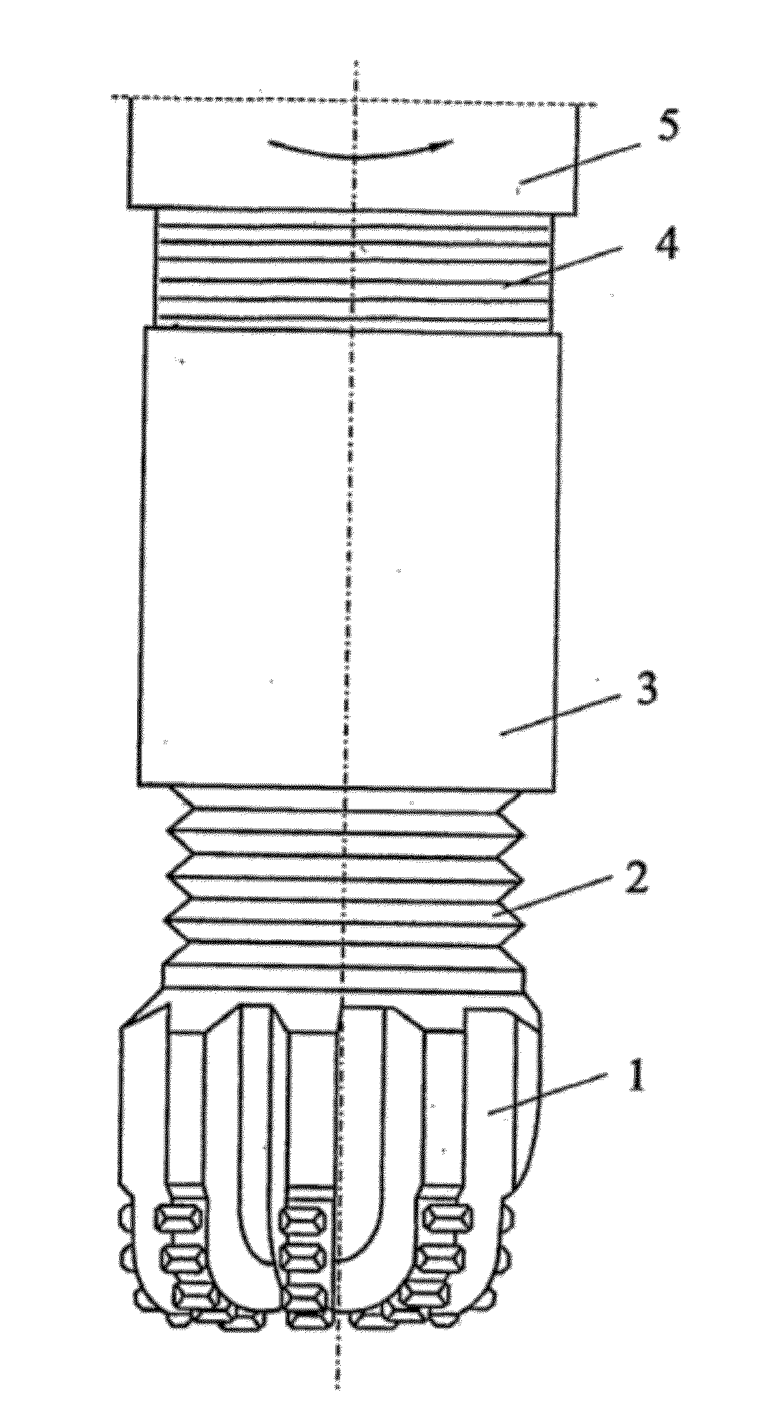
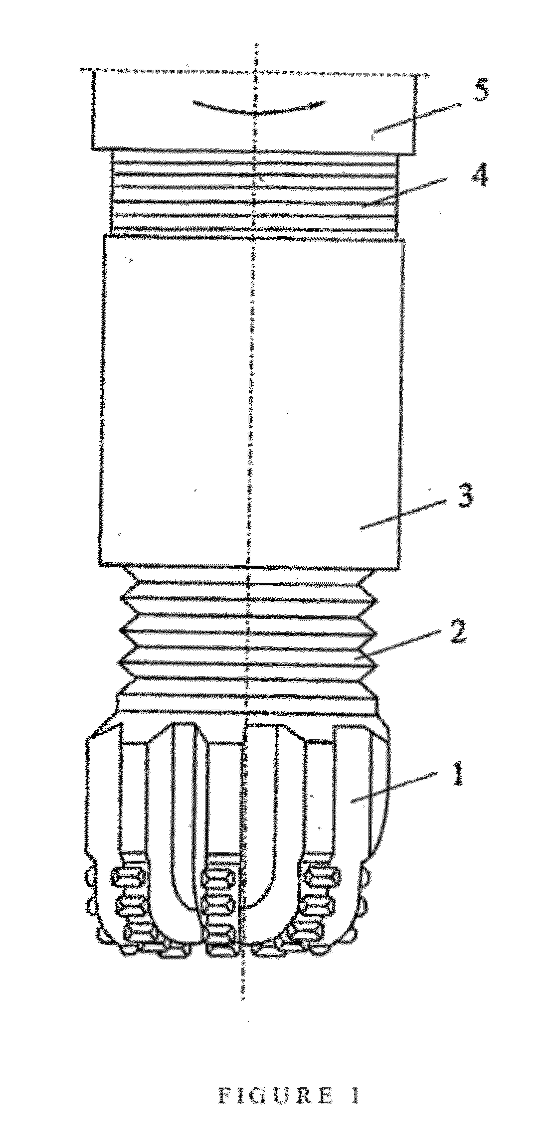
[0029]FIG. 1 shows an illustrative example of a resonance enhanced rotary drilling module according to an embodiment of the present invention. The drilling module is equipped with a rotary drill-bit 1. A vibro-transmission section 2 connects the drill-bit 1 with an oscillator 3 to transmit axially oriented vibrations from the oscillator to the drill-bit 1. A coupling 4 connects the module to a drill-string 5 and acts as a vibration isolation unit to isolate vibrations of the drilling module from the drill-string.

[0030]During a drilling operation, the rotary drill-bit is rotated and an axially oriented dynamic loading is applied to the drill-bit by the oscillator to generate a crack propagation zone to aid the rotary drill bit in cutting though material.

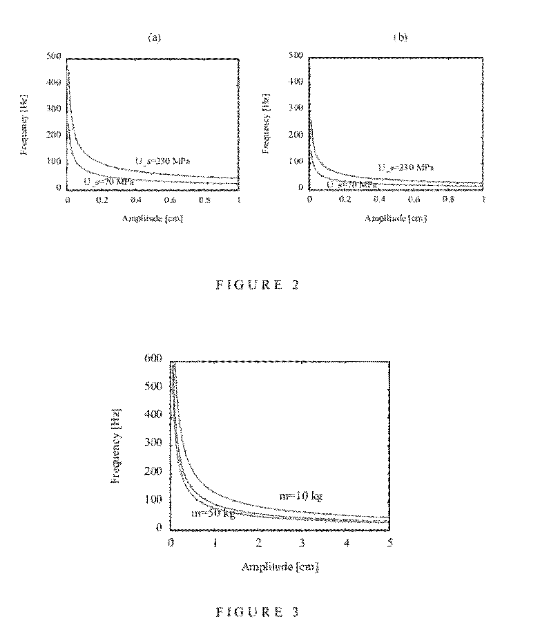
[0031]The oscillator is controlled in accordance with the method of the first aspect of the invention as described in the summary of invention section. The ranges for the frequency and dynamic force are based on the following analysis...


PUM


Abstract

A method for controlling a resonance enhanced rotary drill comprising a rotary drill bit and an oscillator for applying axial oscillatory loading to the rotary drill bit, the method comprising:
    • controlling frequency (f) of the oscillator in the resonance enhanced rotary drill whereby the frequency (f) is maintained in the range
(D2 Us/(8000 πAm))1/2≦f≦Sf(D2 Us/(8000 πAm))1/2
where D is diameter of the rotary drill bit, Us is compressive strength of material being drilled, A is amplitude of vibration, m is vibrating mass, and Sf is a scaling factor greater than 1; and
    • controlling dynamic force (Fd) of the oscillator in the resonance enhanced rotary drill whereby the dynamic force (Fd) is maintained in the range
[(π/4)D2effUs]≦Fd≦SFd[(π/4)D2effUs]
where Deff is an effective diameter of the rotary drill bit, Us is a compressive strength of material being drilled, and SFd is a scaling factor greater than 1,
    • wherein the frequency (f) and the dynamic force (Fd) of the oscillator are controlled by monitoring signals representing the compressive strength (Us) of the material being drilled and adjusting the frequency (f) and the dynamic force (Fd) of the oscillator using a closed loop real-time feedback mechanism according to changes in the compressive strength (Us) of the material being drilled.

Description

FIELD OF INVENTION[0001]The present invention relates to percussion enhanced rotary drilling and in particular to resonance enhanced rotary drilling. Embodiments of the invention are directed to methods and apparatus for controlling resonance enhanced rotary drilling to improve drilling performance. Further embodiments described herein are directed to resonance enhanced rotary drilling equipment which may be controllable according to these methods and apparatus. Certain embodiments of the invention are applicable to any size of drill or material to be drilled. Certain more specific embodiments are directed at drilling through rock formations, particularly those of variable composition, which may be encountered in deep-hole drilling applications in the oil, gas and mining industries.BACKGROUND OF INVENTION[0002]Percussion enhanced rotary drilling is known per se. A percussion enhanced rotary drill comprises a rotary drill bit and an oscillator for applying oscillatory loading to the ...

Claims


Application Information

Patent Timeline
IPC IPC(8): E21B7/24
CPCE21B28/00E21B7/24
Inventor WIERCIGROCH, MARIAN
Owner ITI SCOTLAND
Why Eureka
Try Eureka