

Electrolytic cathode structure and electrolyzer using the same
a cathode structure and electrolyzer technology, applied in the direction of machining electrodes, electrical-based machining electrodes, manufacturing tools, etc., can solve the problems of thin wires stably stabbering into difficult to keep both electrodes in close contact with the ion exchange membrane, and non-uniform inter-electrode distan
- Summary
- Abstract
- Description
- Claims
- Application Information
AI Technical Summary
Benefits of technology
Problems solved by technology
Method used
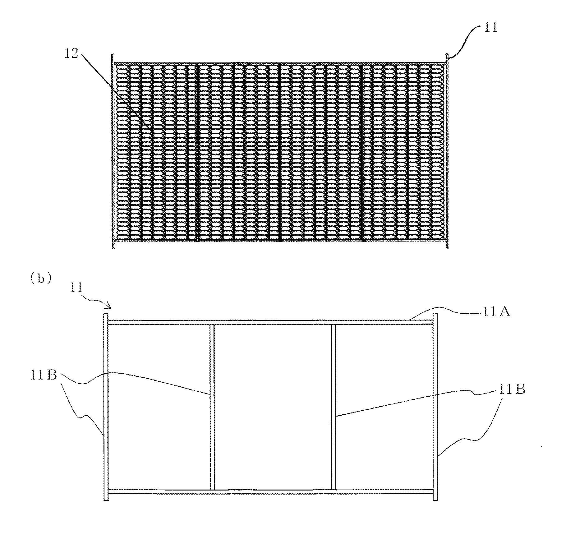
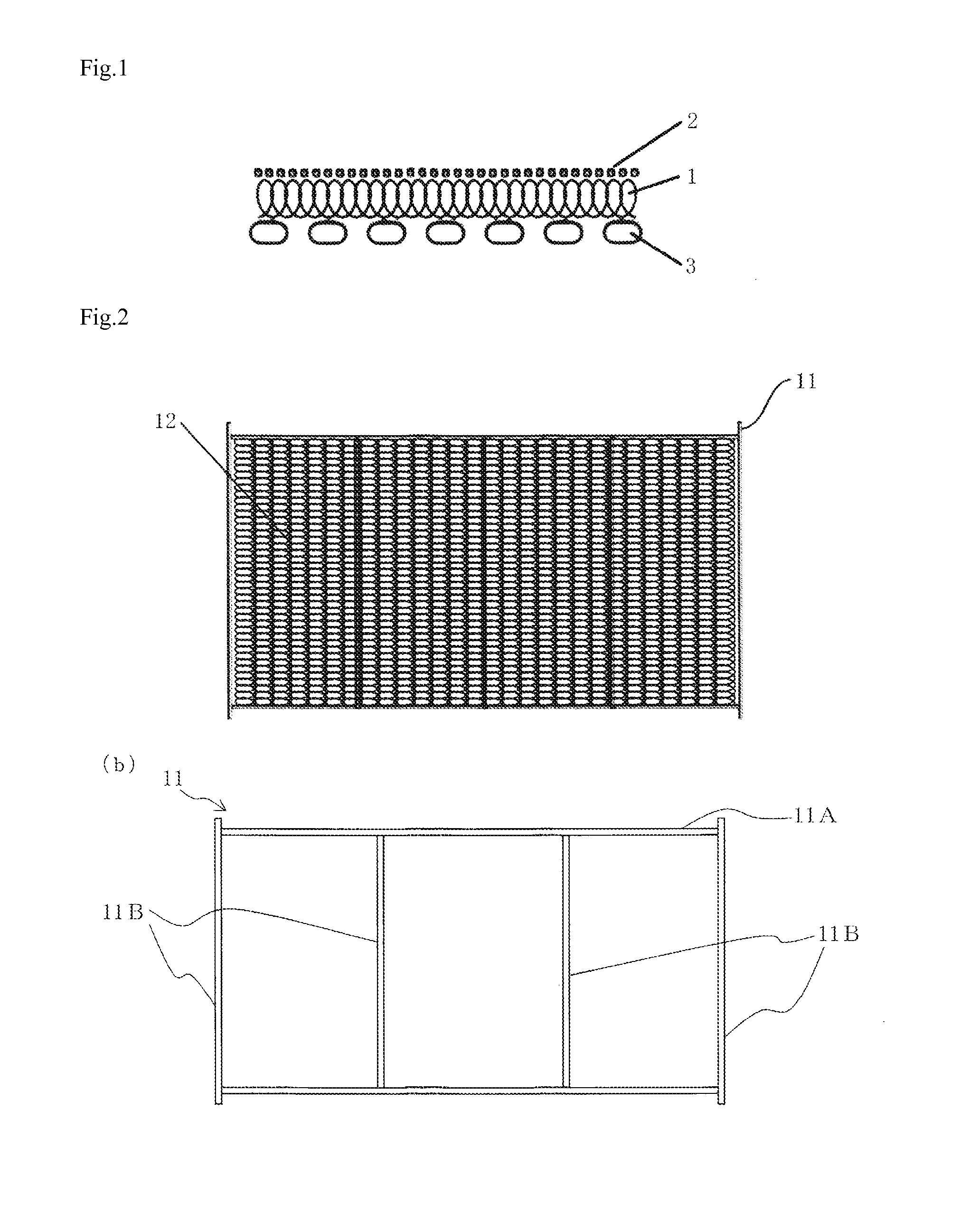
Image

Examples
experimental example 1
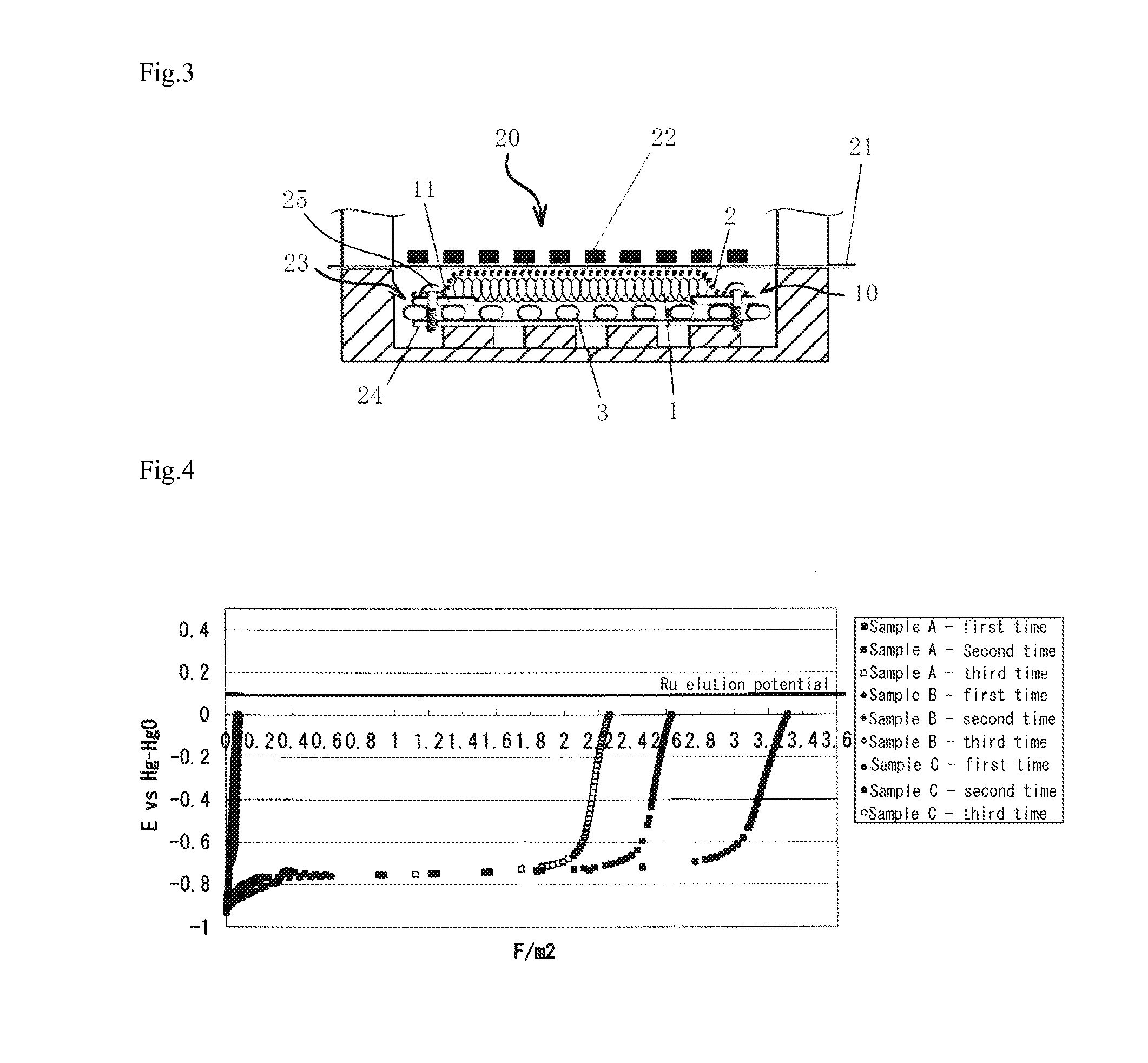
[0041]In accordance with the following procedures, oxidation current was flown to cathode samples below to measure potential changes in the cathodes when anodically polarized. The potential changes were plotted with respect to the total amount of electricity of the flown reverse current to investigate oxidation properties of the cathode. The measurements were performed using 30 wt % NaOH as an electrolyte and a mesh-like nickel electrode as a counter electrode at a temperature of 90° C.
(Procedures)
[0042](1) Preliminary electrolysis (cathodic polarization at 10 kA / m2 for 1 hour).
[0043](2) Starting of anodic polarization (obtaining of potential changes) (until 0 Vvs. Hg—HgO).
[0044](3) Reelectrolysis (cathodic polarization at 10 kA / m2 for 1 hour).
[0045](4) (2) and (3) were repeated, and when anodic polarization was performed three times, the procedures were ended.
(Cathode Samples)
[0046](A) A laminate of a mesh-like Raney nickel alloy electrode (mainly containing Ni and Al and including...
experimental example 2
[0051]To clarify the relationship between a potential reached upon anodic polarization and the degradation range of H.O.V, the cathode samples below were anodically polarized up to a predetermined potential in accordance with the following procedures to measure hydrogen overvoltages (H.O.V) before and after the anodic polarization. The measurements were performed using 30 wt % NaOH as an electrolyte and a mesh-like nickel electrode as a counter electrode at the temperature of 90° C.
(Procedures)
[0052](1) Preliminary electrolysis (cathodic polarization at 10 kA / m2 for 1 hour).
[0053](2) Hydrogen overvoltage measurements.
[0054](3) Anodic polarization up to a predetermined potential (−0.8 V, −0.7 V or −0.6 Vvs. Hg—HgO).
[0055](4) Reelectrolysis (cathodic polarization at 10 kA / m2 for 1 hour).
[0056](5) Hydrogen overvoltage measurements.
[0057](6) (3) to (5) were repeated to measure hydrogen overvoltages after third-time anodic polarization, and then, the procedures were ended.
(Cathode Sample...
experimental example 3
[0060]Using a testing compact electrolyzer having a size of 1 dm2, there was performed short-circuit testing under assumption of the case in which a reverse current flows most heavily in a real machine (the case occurring due to jumper ring operation performed upon maintenance or the like of an electrolyzer) to compare cathode performances before and after the short-circuit testing. The anode used was a chlorine generating electrode with a substrate of titanium expanded metal (DSE JP-202 manufactured by PERMELEC ELECTRODE LTD.), and the ion exchange membrane used was N-2030 manufactured by Dupont Co., Ltd.
(Procedures)
[0061](1) Under conditions of a current density of 6 kA / m2 and a temperature of 90° C.±2° C., the electrolyzer was normally operated using 200±10 g / l of NaCl as an anolyte and 32±1 wt % of NaOH as a catholyte.
[0062](2) A jumper cable was connected and a jumper switch was turned on (starting of short circuit).
[0063](3) Under the following conditions, the electrolyzer was...
PUM
| Property | Measurement | Unit |
|---|---|---|
| Equilibrium | aaaaa | aaaaa |
| Current | aaaaa | aaaaa |
| Area | aaaaa | aaaaa |
Abstract
Description
Claims
Application Information