Liquid Crystal Display Device

Inactive Publication Date: 2012-09-27
JAPAN DISPLAY INC
View PDF8 Cites 30 Cited by
  • Summary
  • Abstract
  • Description
  • Claims
  • Application Information

AI Technical Summary

Benefits of technology

[0027]According to the present invention, the upper surface of the middle frame, on which the liquid crystal display panel is placed, can be planarized. This prevents occurrence of optical leakage arising from deformation of a liquid crystal display panel, whereby a liquid crystal display device with good contrast can be achieved. In addition, a middle frame with a flat upper surface can be made without increasing its overall plate thickness, which allows a liquid crystal display device with good contras

Problems solved by technology

Liquid crystal display devices mounted on vehicles are subjected to vibratio

Method used


Image

  • Liquid Crystal Display Device
  • Liquid Crystal Display Device
  • Liquid Crystal Display Device

Examples


Example

First Embodiment

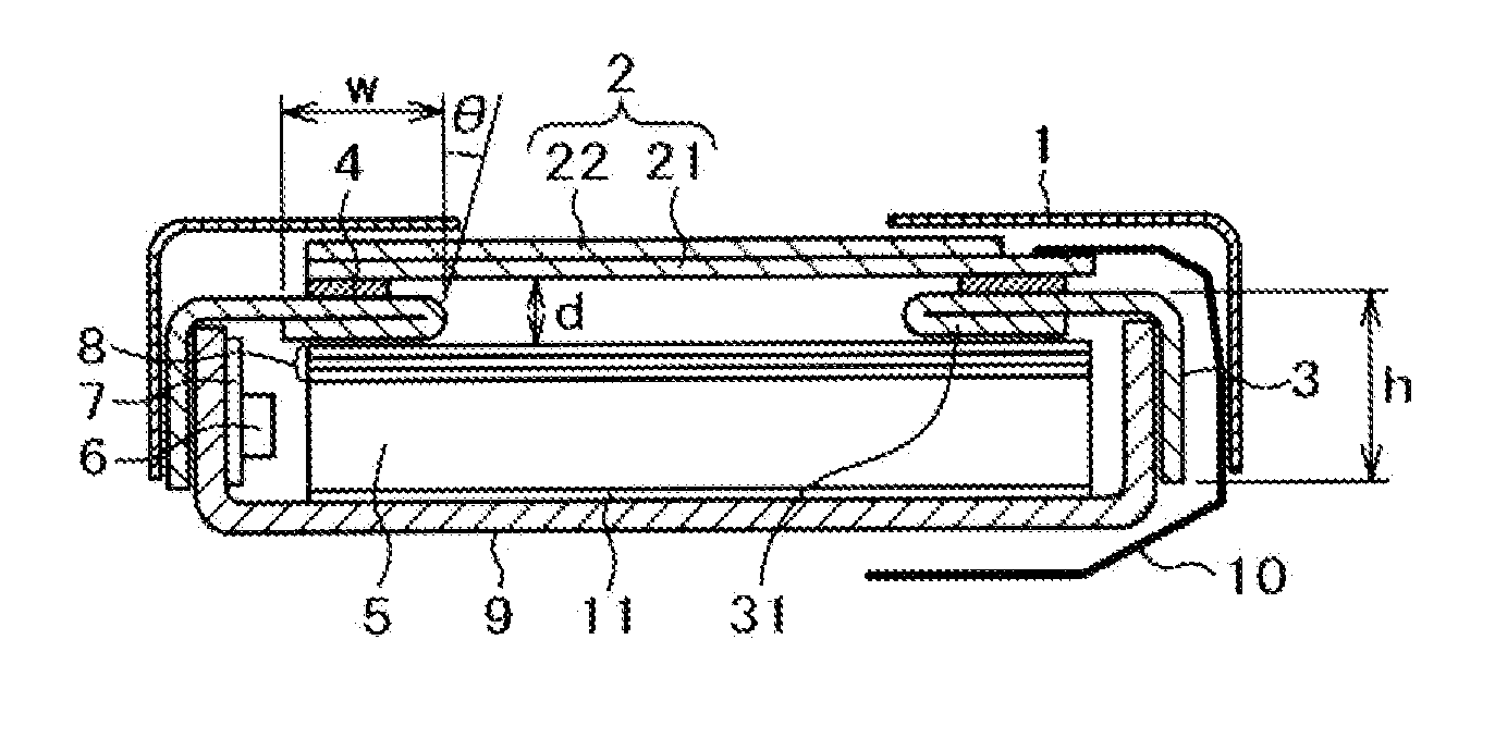
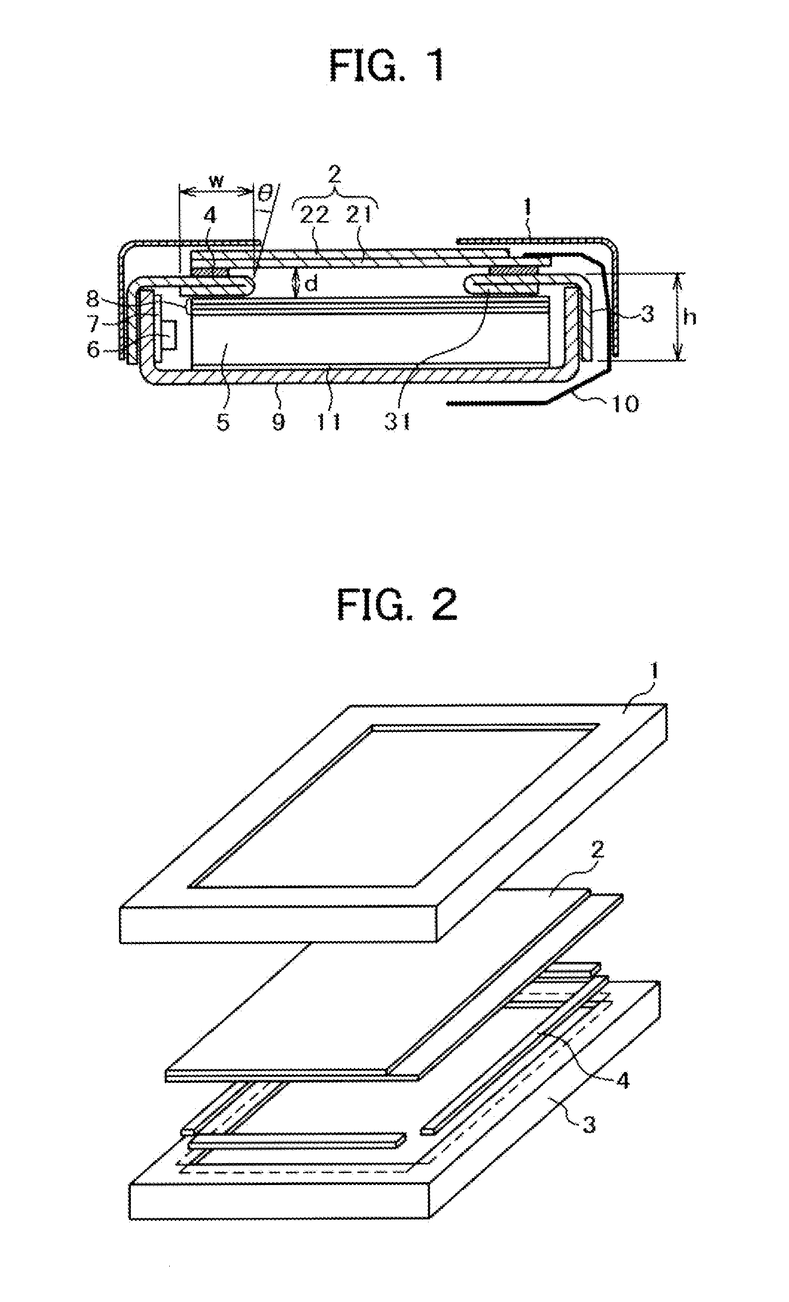
[0039]FIG. 1 is a cross-sectional view showing a liquid crystal display device according to a first embodiment of the present invention. The liquid crystal display device of the first embodiment is basically configured similarly to the device described in FIG. 5. Referring to FIG. 1, an upper frame 1 covers the peripheral area of a liquid crystal display panel 2. The liquid crystal display panel 2 is fixed to a middle frame 3 with cushion tape 4. The peripheral area of the liquid crystal display panel 2 exists between the cushion tape 4 and the upper frame 1. The point where the liquid crystal display device shown in FIG. 1 greatly differs from the conventional one shown at FIG. 8 are the structure of the middle frame 3. In FIG. 1, the upper surface of the middle frame 3 is folded back against itself. The upper surface of the middle frame 3 can thus have an enhanced mechanical strength in the present invention. In addition, after being formed by pressing, the middle ...

Example

Second Embodiment

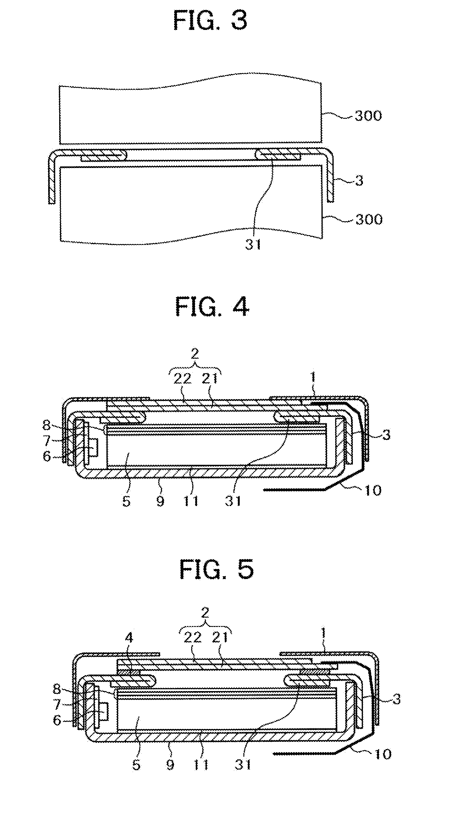
[0047]The liquid crystal display device of the first embodiment is such that the liquid crystal display panel 2 is fixed to the upper portion of the middle frame 3 with the cushion tape 4. Meanwhile, a device to which the present invention is applicable is not limited to the type in which the liquid crystal display panel 2 is fixed with the cushion tape 4. It can be also applied to a type in which the liquid crystal display panel 2 is fixed in place by being clamped with the middle frame 3 and the upper frame 1.

[0048]FIG. 4 is a cross-sectional view showing a liquid crystal display device according to a second embodiment of the present invention. Referring to FIG. 4, a TFT substrate 21 of a liquid crystal display panel 2 is directly disposed on a middle frame 3 without cushion tape 4. An upper frame 1 directly presses down a counter substrate 22 of the liquid crystal display panel 2. The liquid crystal display panel 2 is fixed in place by being clamped with the uppe...


PUM


Abstract

An object of the present invention is to prevent degradation of image contrast arising from deformation of a liquid crystal display panel caused by deformation of the upper surface of the middle frame on which the liquid crystal display panel is mounted.
A liquid crystal display panel is disposed on the upper surface of a middle frame with cushion tape. The middle frame has its upper surface folded back to form a double-layer structure to enhance the strength. Its side surfaces are of a single-layer structure. As the upper surface of the middle frame is planarized and its strength is enhanced, deformation of the liquid crystal display panel can be prevented. This in turn prevents occurrence of optical leakage during black display, thereby preventing the contrast from being degraded.

Description

CLAIM OF PRIORITY[0001]The present application claims priority from Japanese Patent Application JP 2011-063330 filed on Mar. 22, 2011, the content of which is hereby incorporated by reference into this application.BACKGROUND OF THE INVENTION[0002]1. Field of the Invention[0003]The present invention generally relates to liquid crystal display devices, and particularly to a liquid crystal display device adapted to stave off display unevenness arising from distortion of its liquid crystal display panel caused by deformation of the frame accommodating the liquid crystal display panel.[0004]2. Description of Related Art[0005]A display area of liquid crystal display devices is formed from a TFT substrate having pixel electrodes, thin film transistors (TFT), etc. formed in a matrix; a counter substrate opposing the TFT substrate and having color filters, etc. formed at positions corresponding to the pixel electrodes of the TFT substrate; and liquid crystals put between the TFT substrate an...

Claims


Application Information

Patent Timeline
IPC IPC(8): G02F1/13357
CPCG02F1/133308G02F2201/503G02F2001/13332G02F1/13332
Inventor WATANABE, SABURO
Owner JAPAN DISPLAY INC
Why Eureka
Try Eureka