Display device and its producing method and projecting optical apparatus utilizing the same apparatus

A display device and micro-optical technology, applied in optics, projection devices, components of color TVs, etc., can solve the problems affecting the uniformity of the screen 100, reduce the transmittance, and reduce the efficiency of the screen 100, and achieve the best contrast and display. Efficiency, increase the display size, improve the effect of display efficiency

Inactive Publication Date: 2004-11-24
DELTA ELECTRONICS INC
View PDF1 Cites 0 Cited by
  • Summary
  • Abstract
  • Description
  • Claims
  • Application Information

AI Technical Summary

Problems solved by technology

[0009] However, there is an inherent limitation in this technology, that is, when light is incident from the back at a vertical angle, it can easily penetrate the entire screen (such as figure 1 shown)
And when light is incident at a certain angle θ, it is easily absorbed by the light-absorbing material layer 106, thereby reducing its transmittance (such as figure 2 shown)
Depend on figure 1 and figure 2 It can be seen that the larger the incident angle θ of the light is, the thickness of the light-absorbing material layer 106 it needs to face will increase from L1 to L2, which will greatly reduce the efficiency of the entire screen 100, and even affect the uniformity of the entire screen 100

Method used


Image

  • Display device and its producing method and projecting optical apparatus utilizing the same apparatus
  • Display device and its producing method and projecting optical apparatus utilizing the same apparatus
  • Display device and its producing method and projecting optical apparatus utilizing the same apparatus

Examples


Embodiment Construction

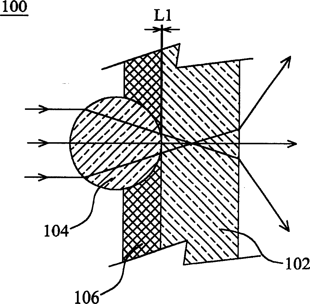
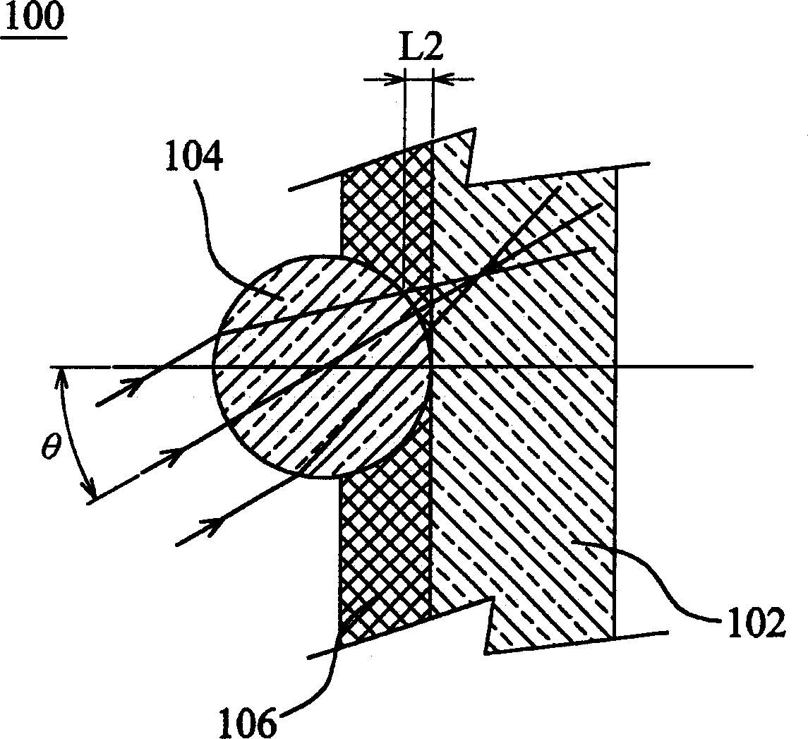
[0040] Figure 4 It is a partial schematic diagram of the display device of the present invention. Such as Figure 4As shown, the display device 200 has an optical focusing structure 206, an optical panel 202, and a light-absorbing material layer 204 with an optical transmission window 208, wherein the optical transmission window 208 is formed by an optical exposure method.

[0041] The optical panel 202 is used to diffuse incident light from one side thereof to the other side. The working principle is that the difference in refractive index between the optical panel 202 and the external air medium makes the light emit from the surface of the optical panel 202 produce a larger scattering angle, so that the effect of wide viewing angle can be achieved.

[0042] The optical focusing structure 206 has a plurality of micro-optical focusing components 210 . Each micro-optics focusing component 210 is used to focus the light from one side to the corresponding other side, so that ...


PUM


Abstract

The display device includes optical focusing structure, optical panel and light absorbing layer. The optical focusing structure is provided with several micro optical focusing modules. The light absorbing layer located between the optical focusing structure and the optical panel is provided with several optical permeating windows corresponding to the micro optical focusing modules separately, with the optical permeating windows being formed via optical exposure process.

Description

technical field [0001] The present invention relates to a display device, a manufacturing method thereof, and a projection optical device using the display device, in particular to a high-contrast display device, a manufacturing method thereof, and a projection optical device using the display device Background technique [0002] Nowadays, the trend of displays is towards thinner and larger sizes. Under this development trend, due to the advantages of thinner thickness and larger size, projection displays gradually replace traditional TVs and become one of the mainstream products of displays. Among the types of projection displays, rear projection displays are the most important. [0003] In today's rear-projection monitors, the screen has the following main functional requirements: [0004] (1) Used to expand the visual range. To increase the viewing angle of the display. [0005] (2) Used to protect the display. To prevent the internal parts of the display from being a...

Claims


Application Information

Patent Timeline
Patent Type & Authority Applications(China)
IPC IPC(8): G03B21/14G03B21/62H04N5/74
Inventor 张绍雄
Owner DELTA ELECTRONICS INC
Why Eureka
Try Eureka