Computer Table for a Furniture

Inactive Publication Date: 2012-10-11
EKORNES
View PDF21 Cites 3 Cited by
  • Summary
  • Abstract
  • Description
  • Claims
  • Application Information

AI Technical Summary

Problems solved by technology

This fixing point is a weak point mechanically speaking, requiring space and is therefore not all

Method used


Image

  • Computer Table for a Furniture
  • Computer Table for a Furniture
  • Computer Table for a Furniture

Examples


Embodiment Construction

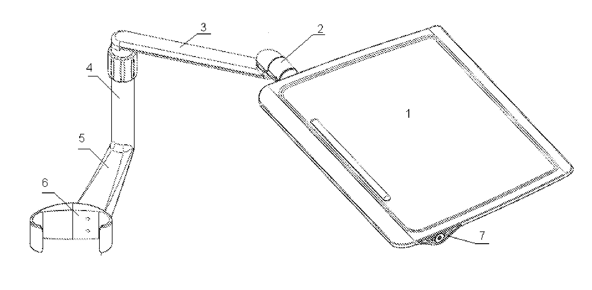
[0013]Computer table of the type described herein comprises a plate that shall hold the computer, more specifically a portable computer, often named laptop. The computer table comprises an arm holding the table top itself, and which again is fixed on a furniture. It must be possible to rotate said arm out and in of the working area of the user, thereby ensuring that it simply can be placed in correct working position and be turned away when it is not in use.

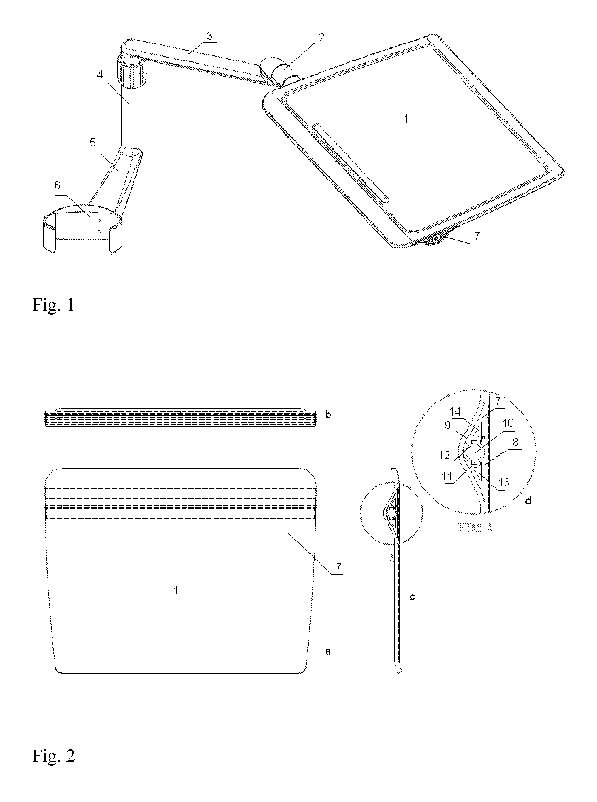
[0014]FIG. 1 shows a computer table according to the invention comprising a table top 1. The table top is fixed to a rotatable joint 2 which again is fixed to an upper arm 3. The upper arm is fixed to a rotating telescopic arm or pillar 4, which again is fixed to a lower arm 5 and a clamp fastener 6. The clamp fastener is estimated to be able to grip round an arm rest, or another suitable component, of a chair, such as a recliner.

[0015]The table top 1 comprises a through profile 7 (FIG. 2) being installed into the table top. The ...


PUM


Abstract

The invention relates to a fixing means for table top comprising a profile (7) installed into the table top (1). The profile can be cast-in into the table top, or the table top can be laminated round the profile. The profile comprises a through bore (10) having a number of longitudinal grooves (11, 12). A shaft (15) is arranged to be directed through the bore (10). A sleeve (18) terminates the shaft (15) at one end as well as a fixing means terminates the shaft at the other end. The sleeve comprises a number of locking lugs (19, 20) arranged to engage into the grooves (11, 12).

Description

FIELD OF THE INVENTION[0001]The present invention relates to a fixing device for table top, a profile being an integral part of the fixing device as well as a table top utilizing the fixing device. The fixing device can be utilized for all types of tables having free-hanging table tops, and especially for computer tables.BACKGROUND OF THE INVENTION[0002]It is prior known tables for computer screens, raising the screen up from the desk. The screen is placed on a small plate. The plate is mounted on a rotating arm, which again is standing on a clamp fastener gripping round the rim of the desk.[0003]In the prior known solutions, the table top is fixed to a rotating joint or an arm by means of a small bracket which again is fixed to the desk with bolts, rivets or similar. This fixing point is a weak point mechanically speaking, requiring space and is therefore not allowing a slim mounting of the plate, and is not much satisfactory from an aesthetic point of view.[0004]Thus, there is a d...

Claims


Application Information

Patent Timeline
IPC IPC(8): A47B13/08
CPCA47B13/08A47B2200/001A47B96/18A47B17/033A47B21/0314A47B23/007A47B83/001A47B2021/0307A47B2200/0075A47B2200/0076
Inventor JARNES, WEBJORN
Owner EKORNES
Why Eureka
Try Eureka