
Divided Conduit

Active Publication Date: 2012-10-18
MILLIKEN & CO
View PDF8 Cites 9 Cited by
  • Summary
  • Abstract
  • Description
  • Claims
  • Application Information

AI Technical Summary

Problems solved by technology

However, it has been found that it is difficult to merely insert a second cable into a conduit that already contains a first cable.
When a rope is blown or “snaked” into a conduit already containing a cable (or when a second cable is “snaked” through a conduit with a pre-laid cable), the rope (or cable) is often impeded by the first cable.
In such cases, the rope (or second cable) becomes tangled with, or twisted around, the first cable, causing damage to the cables.
A problem has been encountered in that when conduit is placed over long distances, undulations will invariably occur therein.
Also, planned curves, such as at underpasses or the like, will often be encountered rendering the placement of known dividers therein difficult, if not impossible.

Method used


Image

  • Divided Conduit
  • Divided Conduit
  • Divided Conduit

Examples


Embodiment Construction

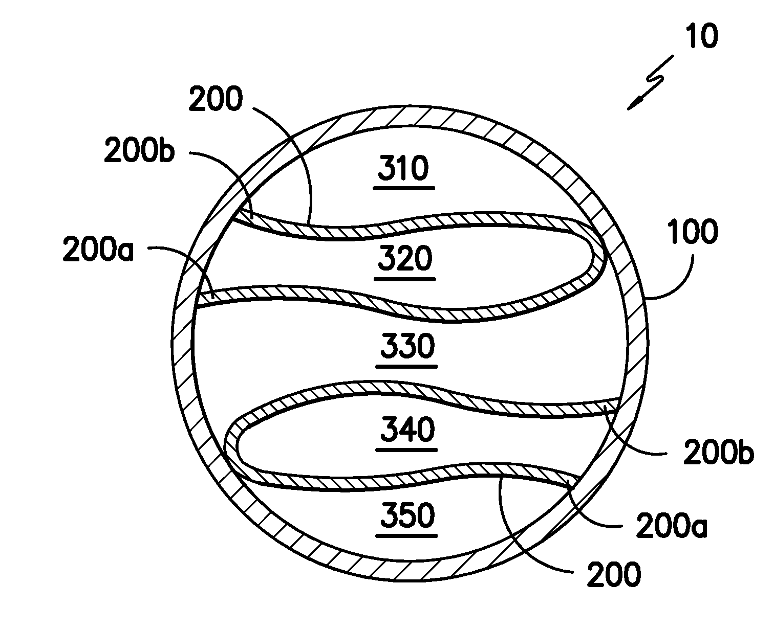
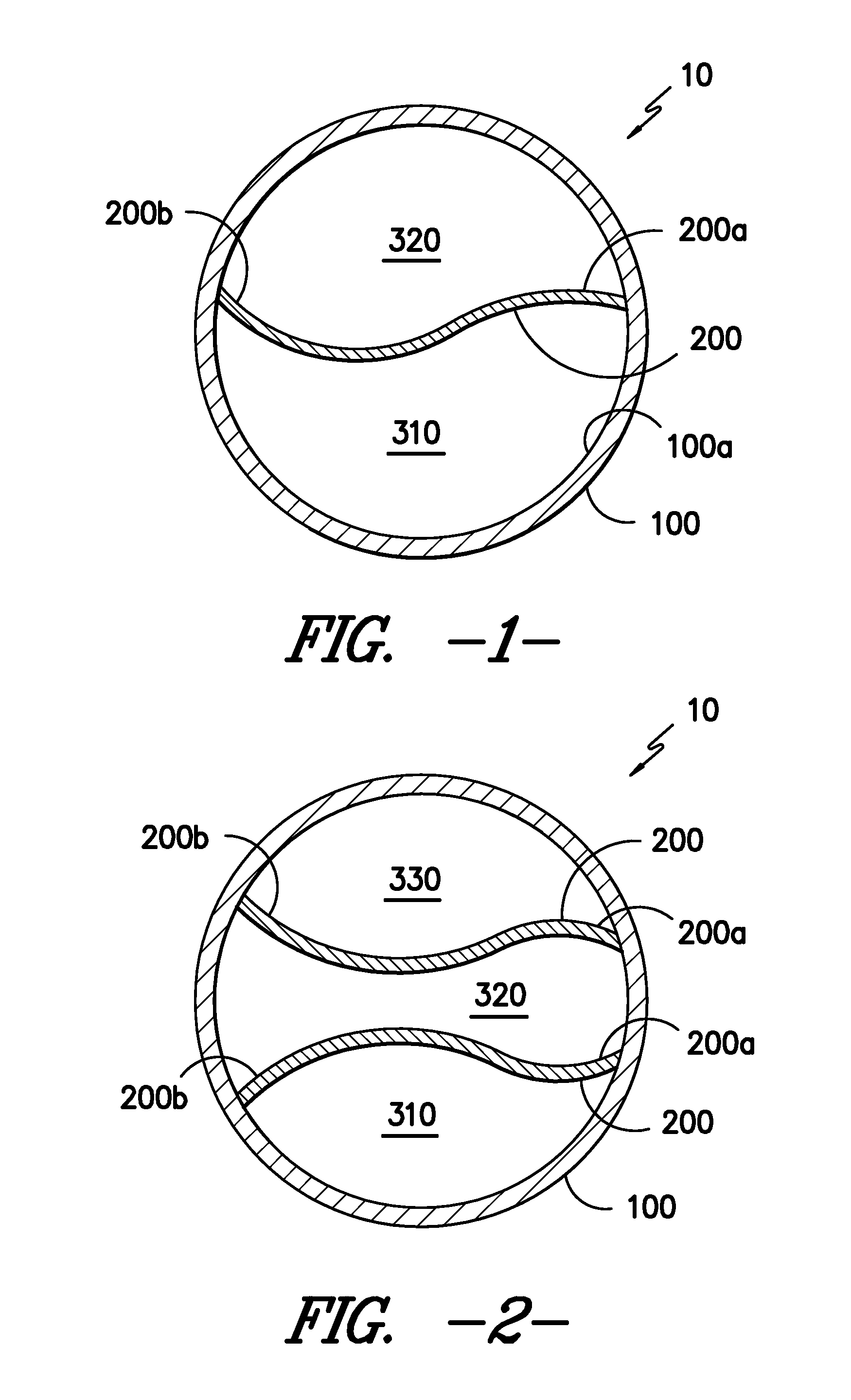
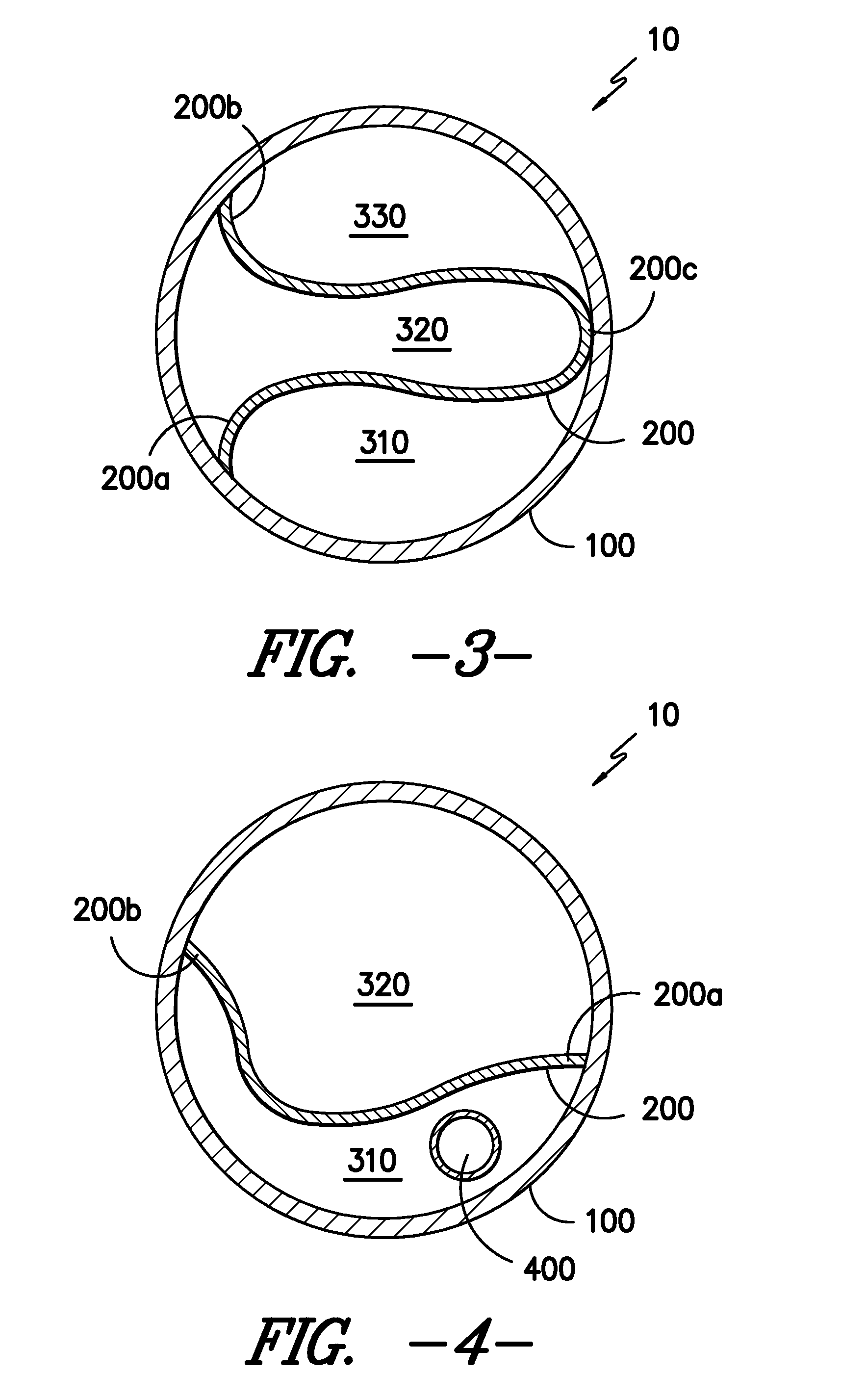
[0015]The divided conduits described herein are readily manufactured. Each divided conduit provides a structure that allows cables to be pulled through without snagging or excessive heat build-up due to friction. In addition, the divided conduits do not allow contact or alternation losses between adjacent cables in other channels of the conduit.

[0016]The term “strip-shaped substrate” refers to a long strip of flexible material made of any suitable material such a textile or film. The term “longitudinal edges” refers to the edges along the length of the strip-shaped substrate. The term “longitudinal axis” refers to the axis of the strip-shaped substrate along its length. “Integral”, in this application, means that two of more materials are connected with each other without the further use of any glues or adhesives. The divided conduit may be considered to be integral.

[0017]Referring now to FIG. 1, there is shown one embodiment of the divided conduit 10. In FIG. 1, the conduit 100 con...


PUM


Abstract

A divided conduit containing a thermoplastic conduit and at least one strip-shaped textile. The strip-shaped substrate may be a strip-shaped textile or a strip-shaped film and has a first longitudinal edge and a second longitudinal edge which are adhered to or embedded into the inner surface of the conduit forming at least two flexible, longitudinal channels for enveloping cables or other elongated structures.

Description

RELATED APPLICATIONS[0001]This application is related to the application with attorney docket number 6574, “Process for Forming a Divided Conduit” filed on Apr. 18, 2011.TECHNICAL FIELD[0002]The present disclosure generally relates to divided conduits into which cables, such as fiber optic cables, coaxial cables, electrical cables, electrical wiring, and the like, may be positioned. More particularly, the present disclosure relates to divided conduits having a strip-shaped substrate attached to the conduit on its longitudinal edges separating the conduit into two or more longitudinal channels.BACKGROUND[0003]Cable, such as fiber optic communication cable, is often provided underground in great lengths, and may even extend for many miles. It is known in the art to bury the cable in the ground so that the area above-ground is not cluttered with the cable and its respective support apparatus. Furthermore, by positioning the cable underground, it is more protected from the weather and o...

Claims


Application Information

Patent Timeline
IPC IPC(8): H02G3/04
CPCH02G9/065
Inventor HEPFINGER, JOHN M.ZEILER, BERNHARD
Owner MILLIKEN & CO
Learn More