Temporary abutment with combination of scanning features and provisionalization features

a technology of provisionalization and abutment, which is applied in the field of temporary abutments with scanning features and provisionalization features, and can solve problems such as discrepancies

Active Publication Date: 2012-11-22
BIOMET 3I LLC
View PDF9 Cites 39 Cited by
  • Summary
  • Abstract
  • Description
  • Claims
  • Application Information

AI Technical Summary

Benefits of technology

The patent describes methods for creating patient-specific abutments for dental implants. These methods involve attaching a temporary abutment to the implant and designing a temporary prosthesis to heal the surrounding tissue. The temporary abutment includes an informational marker that indicates the characteristics of the implant. The methods also involve scanning the mouth and analyzing the data to create a three-dimensional model of the mouth. This model is then used to design the patient-specific abutment. The technical effects of these methods include improved accuracy and efficiency in the design and manufacturing of dental implants.

Problems solved by technology

The technical problem addressed in this patent text is the discrepancy between the emergence profile of the patient's gingiva and the installed prosthesis, which can require additional visits with the dentist or compromise the aesthetic outcome of the installed prosthesis. There is also a need to resolve problems related to temporization of a prosthesis and tying in scanning technologies with the temporization of prostheses.

Method used


Image

  • Temporary abutment with combination of scanning features and provisionalization features
  • Temporary abutment with combination of scanning features and provisionalization features
  • Temporary abutment with combination of scanning features and provisionalization features

Examples


Embodiment Construction

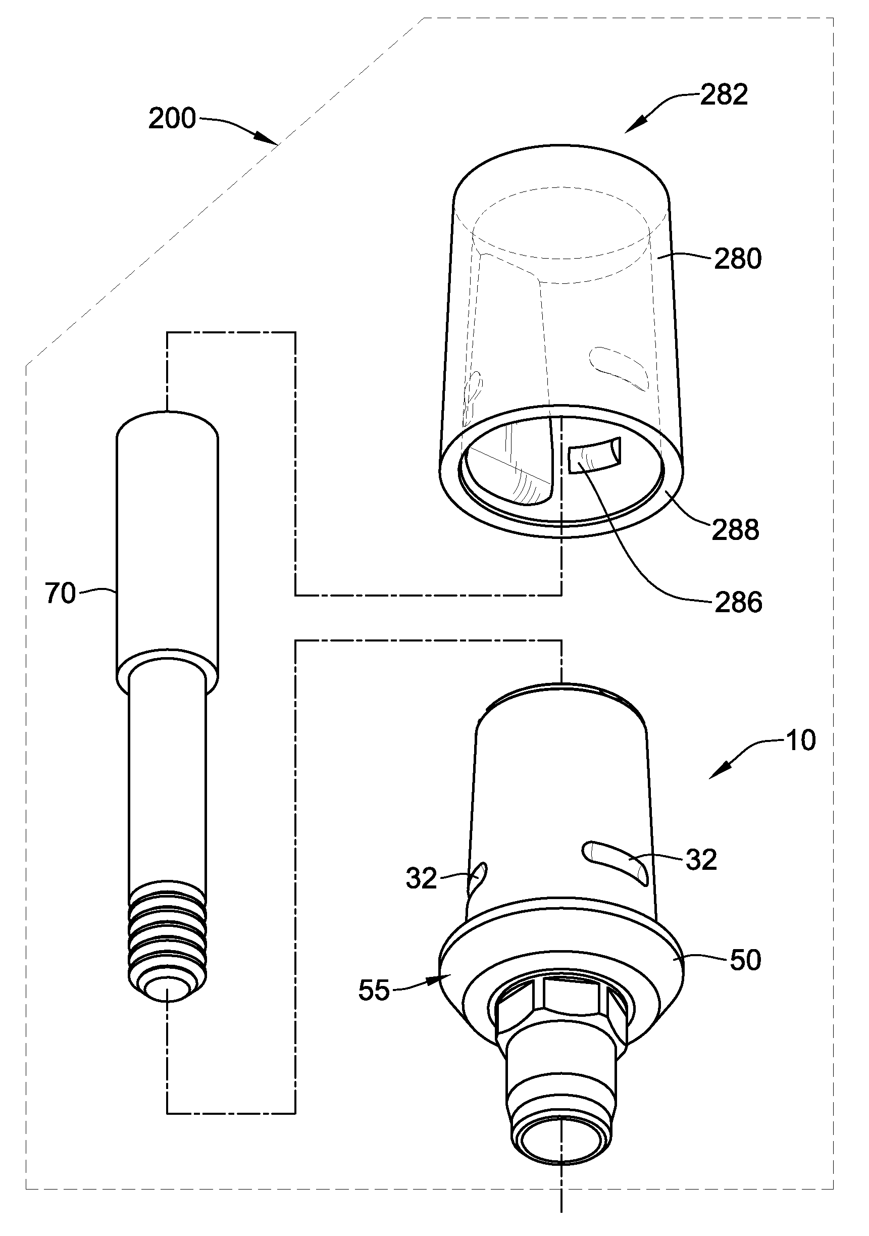
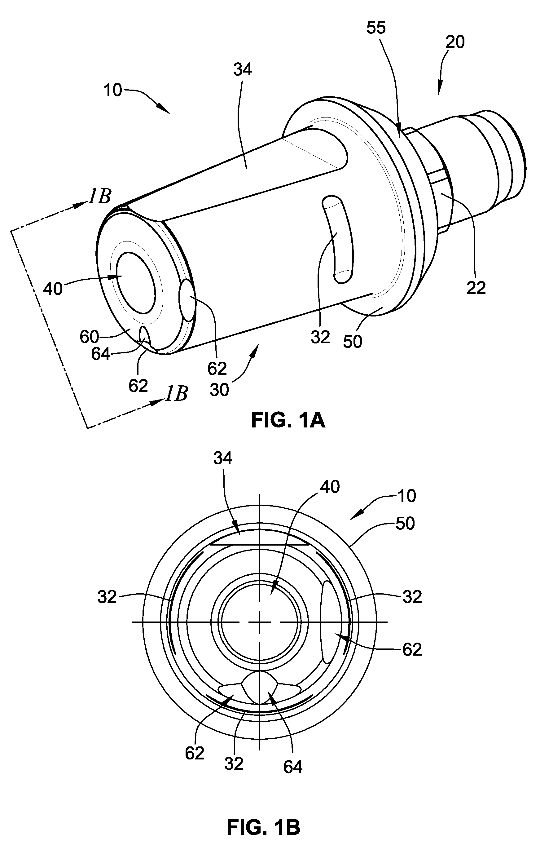
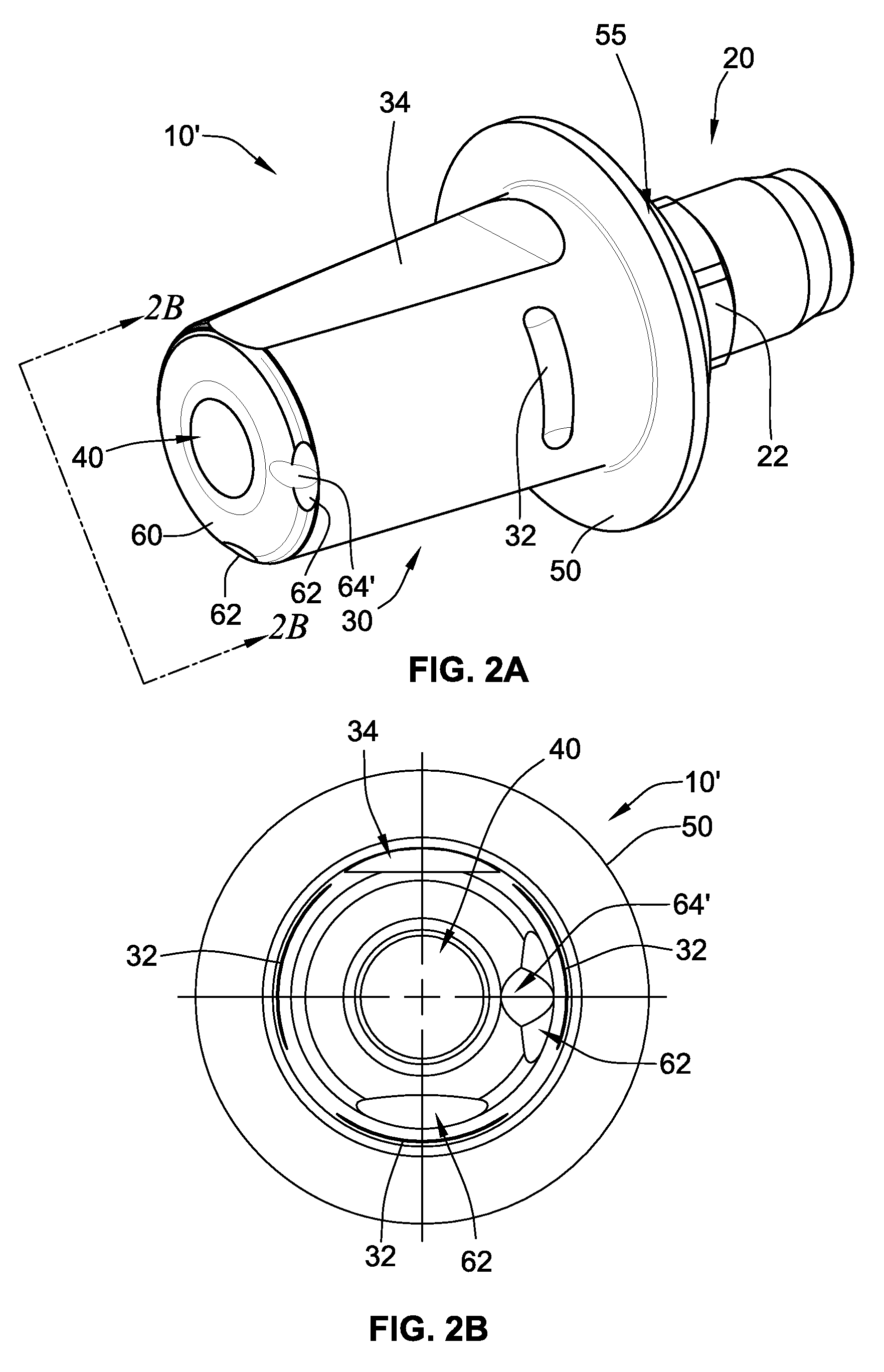
[0041]Referring to FIGS. 1A and 1B, a temporary abutment 10 of the present disclosure (like other temporary abutments of the present disclosure) may be used for at least four purposes, which will be explained in more detail below. First, the temporary abutment 10 may serve as a gingival healing abutment as its exterior surface is contoured to aid in the healing of a patient's gingival tissue. Second, the temporary abutment 10 may serve as a temporary prosthesis (i.e., it provides a convenient mount for removably attaching an acrylic portion having an anatomical tooth shape). Third, the temporary abutment 10 serves as a scanning member to permit a clinician to use one or more scanning techniques to obtain necessary information about the underlying implant's location and orientation for use in developing permanent prosthetic components. And fourth, the temporary abutment 10 may serve as a permanent abutment providing a convenient mount for a permanent prosthesis having an anatomical t...


PUM


Abstract

A lower region of a temporary abutment includes an anti-rotational feature for non-rotationally mating with a dental implant. An upper region of the temporary abutment includes a first anti-rotational structure and at least one retention groove. A top surface of the temporary abutment includes one or more informational markers that provide information concerning the dental implant. A temporary abutment cap is configured to be coupled to the upper region of the temporary abutment. The temporary abutment cap has at least one projection configured to mate with the at least one retention groove of the temporary abutment. The temporary abutment cap has a second anti-rotational structure that is configured to slideably engage the first anti-rotational structure of the temporary abutment. The temporary abutment cap is configured to be coupled with a temporary prosthesis such that the temporary prosthesis and the temporary abutment cap are removable from the temporary abutment.

Description


Claims


Application Information

Patent Timeline
Owner BIOMET 3I LLC
Why Eureka
Try Eureka