Vise with push device

a push device and push technology, applied in the field of push devices, can solve the problems of longer assembly time and higher manufacturing cos

Inactive Publication Date: 2013-02-14
LEE CHIN YUAN
View PDF2 Cites 4 Cited by
  • Summary
  • Abstract
  • Description
  • Claims
  • Application Information

AI Technical Summary

Benefits of technology

[0008]The primary object of the present invention is to provide a push unit for the vise and the movable jaw is movable toward or away from the fixed jaw by the push unit....

Problems solved by technology

However, the push device includes too many parts and has complicated ...

Method used


Image

  • Vise with push device
  • Vise with push device
  • Vise with push device

Examples


Embodiment Construction

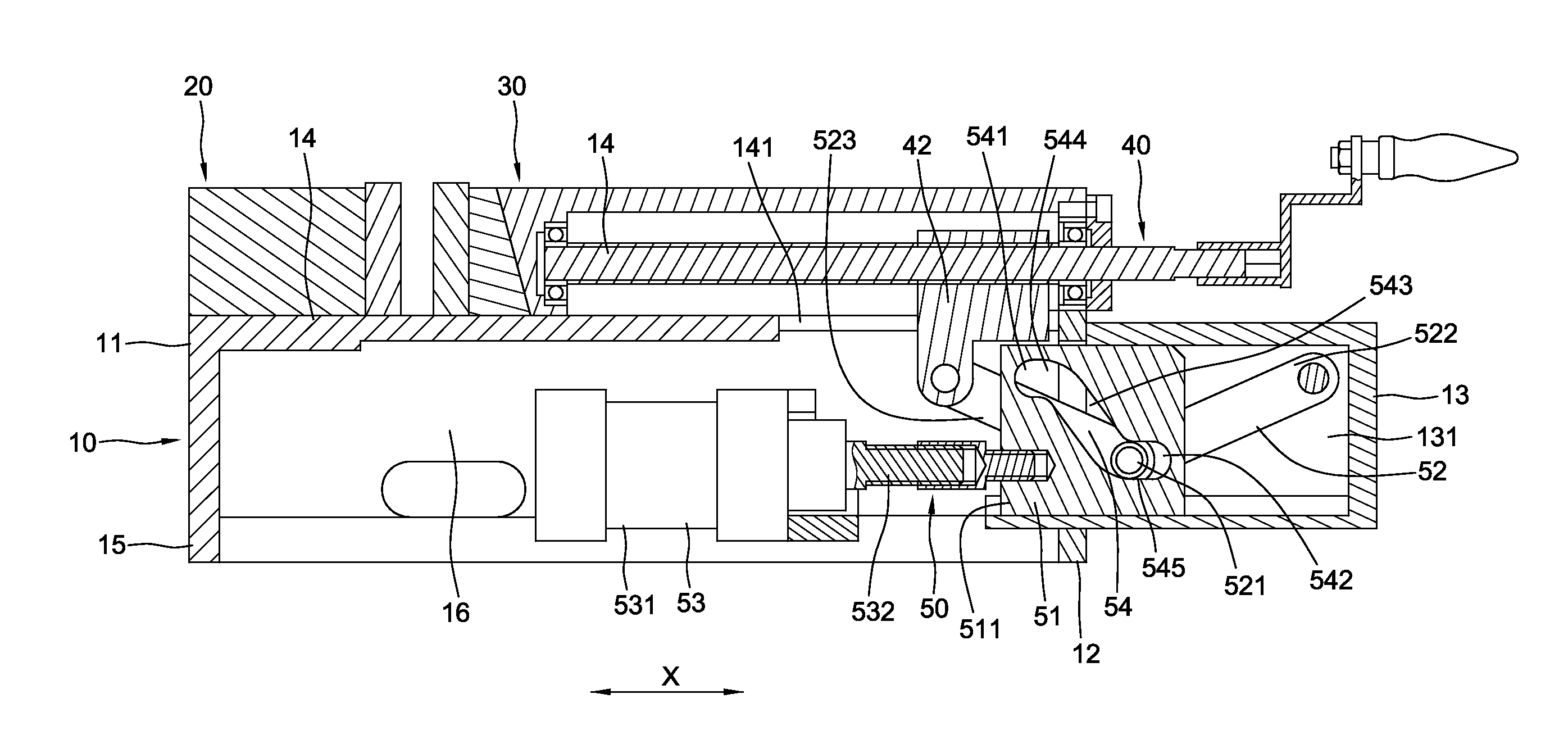
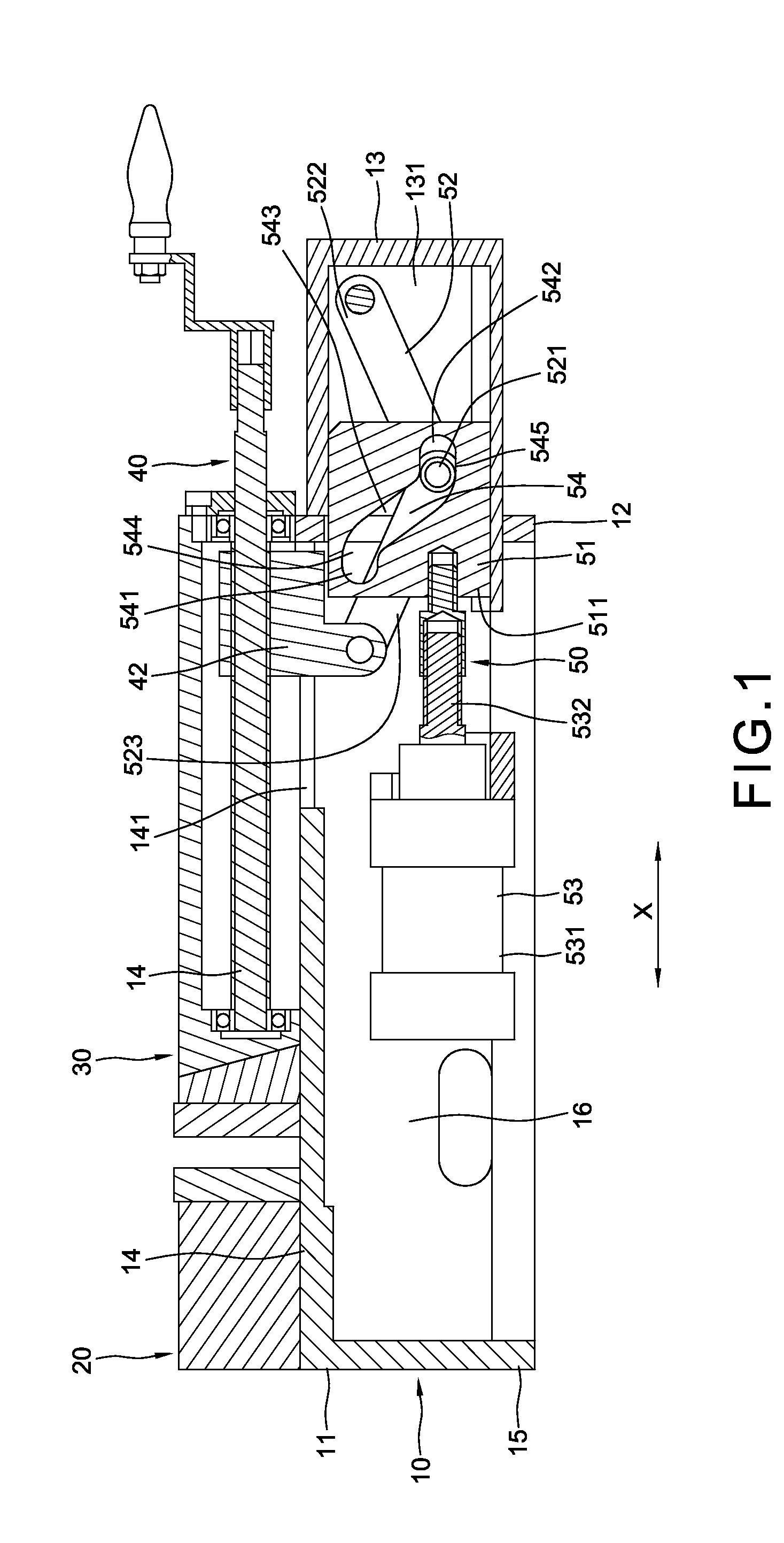
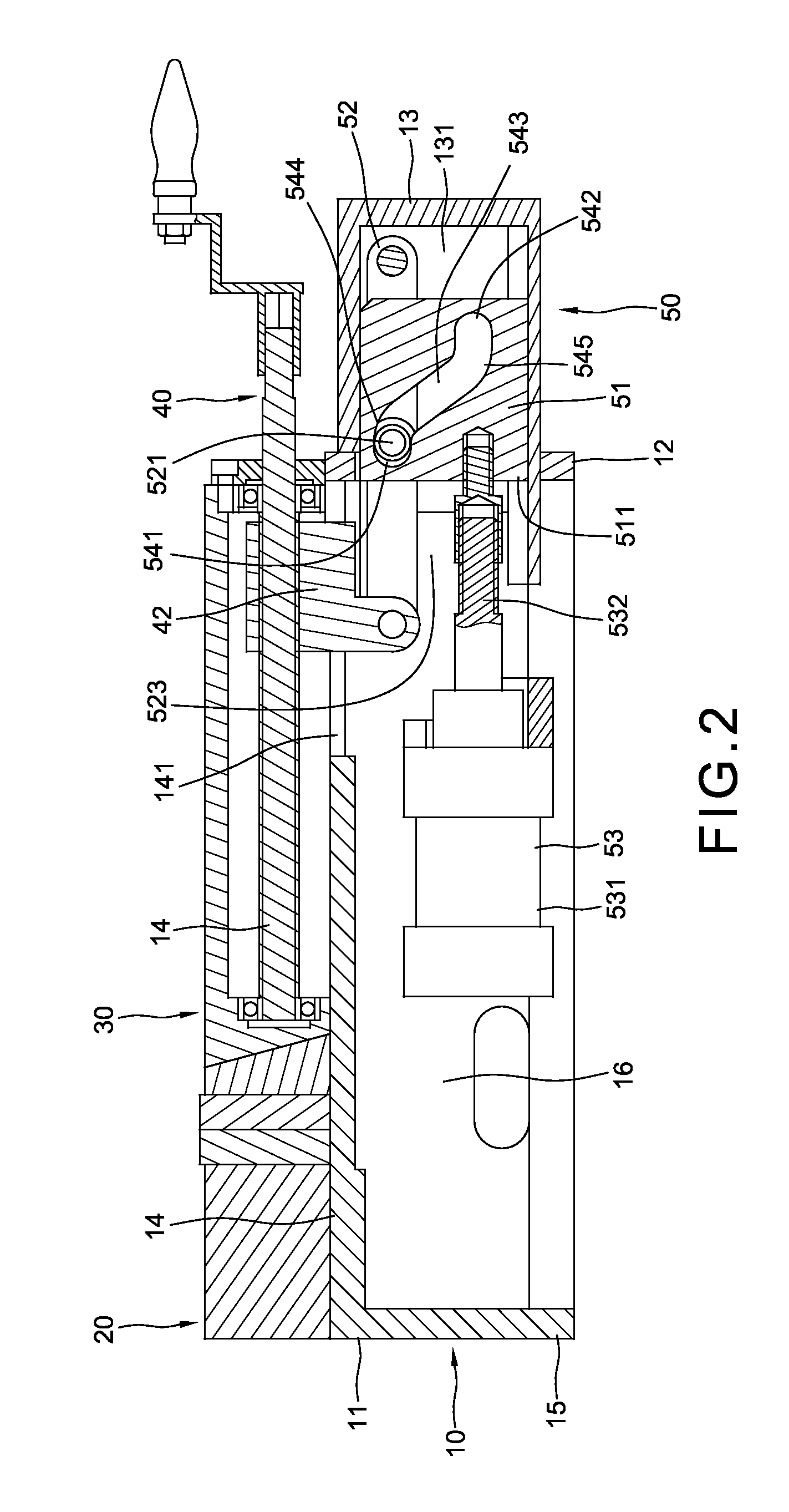
[0013]Referring to FIG. 1, the vise of the present invention comprises a body 10 extending along a longitudinal direction “X” and the body 10 has a first end 11 and a second end 12 which is located in opposite and along the longitudinal direction “X” to the first end 11. A fixed jaw 20 is fixed to the first end 11 and the second end 12 has a guide member 13 located along the longitudinal direction “X”. The guide member 13 of the body 10 is a hollow member and has a guide hole 131 which extends along the longitudinal direction “X”. The body 10 has a top board 14 and multiple end boards 15 extend downward from the top board 14. A space 16 is defined between the top board 14 and the multiple end boards 15. The top board 14 has a slot 141 which reaches the space 16.

[0014]A movable jaw 30 is connected to the body 10 and located corresponding to the fixed jaw 20. The movable jaw 30 is moveable along the top board 14.

[0015]A driving unit 40 has a threaded rod 41 which is co-axially connect...


PUM


Abstract

A vise includes a body and a fixed jaw connected to the body, a movable jaw, a driving unit, and a push unit. The body has a guide member and the driving unit has a threaded rod which is co-axially connected to the movable jaw. A locking member is threadedly mounted to the threaded rod. The push device has a slide mounted to the guide member, a joint member connected to the slide and a cylinder connected to the slide. The slide has a groove and the joint member has a pivot which is engaged with the groove. When activating the cylinder, the movable jaw is moved toward to or away from the fixed jaw by the joint member and the locking member, and the clamping force is magnified.

Description

BACKGROUND OF THE INVENTION[0001](1) Field of the Invention[0002]The present invention relates to a vise, and more particularly, to a vise with a push device which magnifies the force for clamping objects.[0003](2) Description of the Prior Art[0004]One of the conventional vises is disclosed in Taiwan Utility Model No. M344941 and discloses a body with a threaded rod located within the body, a movable jaw threadedly connected to the threaded rod, a push rod located in the threaded rod, and a push device which is located corresponding to the push device. The push device has an activation member and a joint member, wherein the activation member is driven by the push rod and the joint member is activated by the activation member. When the push rod is activated, the activation member drives the joint member which acts between an extended position and a folded position. The actions of the joint member drive the threaded rod so that the movable jaw is moved toward or away from the fixed ja...

Claims


Application Information

Patent Timeline
IPC IPC(8): B25B1/24
CPCB25B1/02B25B1/125B25B1/103
Inventor LEE, CHIN-YUAN
Owner LEE CHIN YUAN
Why Eureka
Try Eureka