Golf ball having non-concentric parting line

a golf ball and non-concentric technology, applied in the field of golf ball non-concentric parting lines, can solve the problems of golf ball dimple pattern formation on the periphery of the golf ball cover, molding flash, and other projecting surface imperfections, and achieve the effect of negatively affecting the quality of the finished golf ball

Active Publication Date: 2013-02-14
ACUSHNET CO
View PDF0 Cites 4 Cited by
  • Summary
  • Abstract
  • Description
  • Claims
  • Application Information

AI Technical Summary

Benefits of technology

[0013]The present invention is directed to a golf ball comprised of non-concentric arcs defining a non-planar parting line on its spherical surface. Said parting line is useful for dimple designs where one or more manufacturing vulnerabilities are encountered during cavity production. These obstacles most commonly lead to cavity damage and subsequently, negatively influence finished golf ball quality.

Problems solved by technology

In addition, the cover blanks are simultaneously molded into conformity with the interior configuration of the hemispherical molds which results in the formation of the dimple pattern on the periphery of the golf ball cover.
As in all molding operations, when the golf ball is removed from the hemispherical molds subsequent to the molding operations, it will have molding flash, and possibly other projecting surface imperfections.
In other words, a grinding operation may have difficulty reaching into the dimples of the golf ball to remove the molding flash without ruining the golf ball cover.
While this could potentially improve compliance with the symmetry, they did not sufficiently improve dimple coverage, since the parting lines included straight segments that did not permit interdigitation of dimples from opposite sides of the equator.
A stepped path often results in a greater loss of dimple coverage than a straight path because it discourages interdigitation for a larger number of dimples.
These obstacles most commonly lead to cavity damage and subsequently, negatively influence finished golf ball quality.
Ones such vulnerability is having a large size disparity between dimples in one hemisphere and adjacent dimples from the opposing hemisphere.
A second possible vulnerability is if adjacent dimples from opposing hemispheres are heavily weighted towards one hemisphere over the other.
A third possible vulnerability is if the wave design utilizing an arc concentric to the dimple perimeter provides inadequate relief from said perimeter.

Method used


Image

  • Golf ball having non-concentric parting line
  • Golf ball having non-concentric parting line
  • Golf ball having non-concentric parting line

Examples


Embodiment Construction

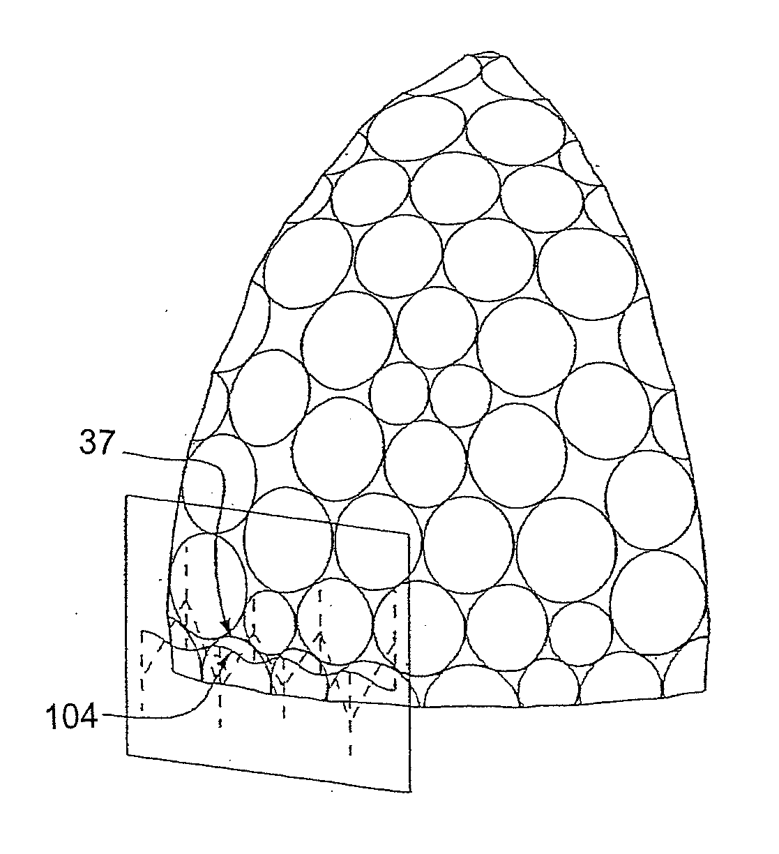
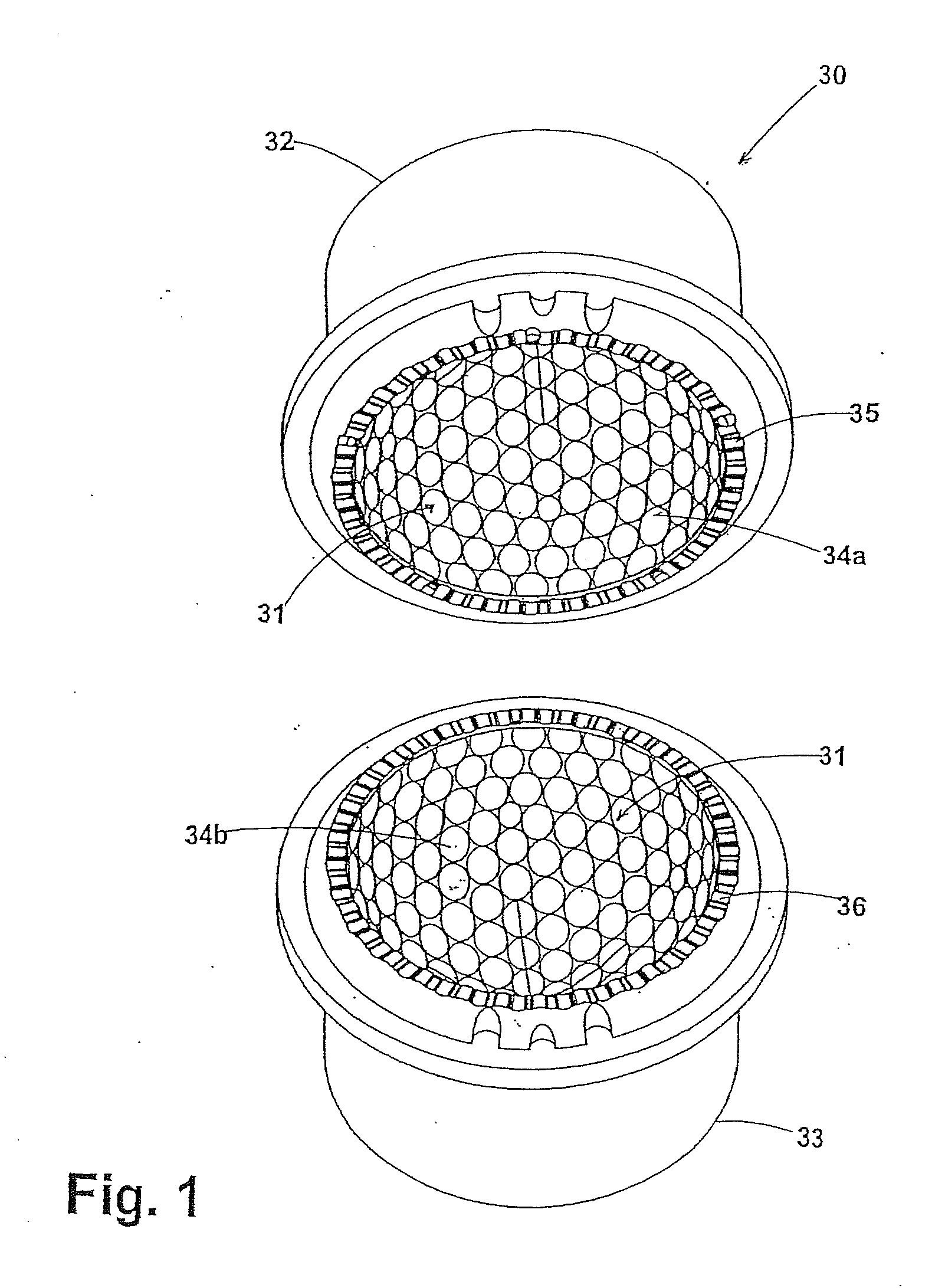
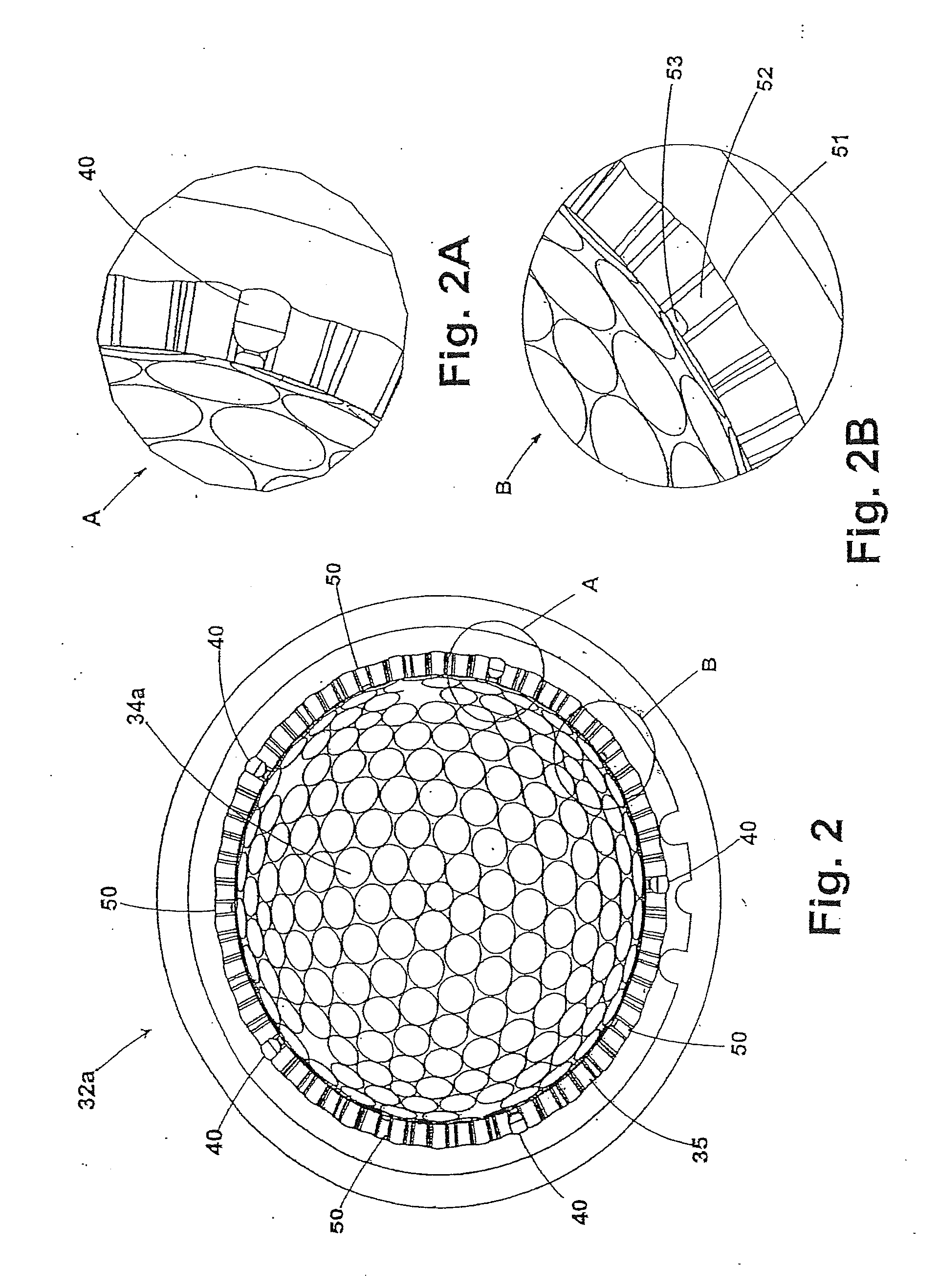
[0048]Referring to FIGS. 1 to 4, wherein an improved mold is shown, with the mold being indicated by the reference numeral 30, the mold 30 having a spherical cavity 31 which is used to form a cover for a golf ball wherein the mold 30 comprises hemispherical mold halves, an upper mold half 32 and a lower mold half 33, both halves having interior dimple cavity details 34a and 34b respectively with the details of the upper mold half 34a shown in FIGS. 2, 2A and 2B, for a mold designed to form a castable cover over a core, and in FIGS. 3 and 3A, for a mold designed to form a cover made from Surlyn, and when these halves are mated they define a dimple arrangement therein. Any dimple arrangement, such as icosahedral, octahedral, cube-octahedral, dipyramid, and the like could be used. Although the preferred dimple is circular when viewed from above, the dimples may be oval, triangular, square, pentagonal, hexagonal, heptagonal, octagonal, etc. Possible cross-sectional shapes include, but a...


PUM


Abstract

The present invention is directed to a golf ball comprising of non-concentric arcs defining a non-planar parting line on its spherical surface resulting in having a large size disparity between dimples in one hemisphere and adjacent dimples from the opposing hemisphere. The parting line is produced by a pair of adjacent dimples, wherein D indicates dimples and N indicates dimples from the Northern hemisphere and those from the Southern hemisphere are indicated by S. A large disparity may be created, if the following condition is satisfied:
D(N)D(S)>1.25orD(N)D(S)<0.80.

Description

[0001]This application is a continuation-in-part of co-pending U.S. application Ser. No. 12 / 755,605 which was filed Apr. 7, 2010, which is a continuation-in-part of co-pending U.S. application Ser. No. 12 / 199,822 which was filed Aug. 28, 2008, now abandoned, which is a divisional of U.S. application Ser. No. 11 / 273,175 which was filed Nov. 14, 2005, now abandoned, which is a continuation-in-part of U.S. application Ser. No. 10 / 797,796 filed on Mar. 10, 2004, and is now Patent No. 7,422,529 and is incorporated herein in its entirety by express reference thereto.FIELD OF THE INVENTION[0002]The invention relates in general to an improved mold for forming a golf ball having a non-planar parting surface for seamless appearing golf balls, and more particularly, to a non-planar parting line formed by non-concentric arcs.BACKGROUND OF THE INVENTION[0003]The usual golf ball manufacturing techniques include several different steps, depending on the type of ball, such as one, two, three or eve...

Claims


Application Information

Patent Timeline
Patent Type & Authority Applications(United States)
IPC IPC(8): A63B37/14A63B37/12
CPCA63B37/0004A63B47/00A63B37/0006
Inventor MADSON, MICHAEL R.NARDACCI, NICHOLAS M.HUNT, DAVID P.
Owner ACUSHNET CO
Why Eureka
Try Eureka