Vacuum interrupter

a vacuum interrupter and bellows technology, applied in the direction of air breakers, high-tension/heavy-dress switches, contact vibration/shock damping, etc., can solve the problem of difficult buckling, and achieve the effect of preventing buckling of the bellows and increasing the size of the vacuum interrupter

Active Publication Date: 2013-02-28
MITSUBISHI ELECTRIC CORP
View PDF11 Cites 5 Cited by
  • Summary
  • Abstract
  • Description
  • Claims
  • Application Information

AI Technical Summary

Benefits of technology

[0010]According to the vacuum interrupter of the present invention, the increase of the vacuum interrupter size is prevented as well as the buckling of the bellows can be prevented.

Problems solved by technology

According to this structure, because the inner side of the bellows is in a vacuum state, and the outer side of the bellows is in an atmospheric air or a pressurized insulation gas state, the buckling is difficult to occur.

Method used


Image

  • Vacuum interrupter
  • Vacuum interrupter
  • Vacuum interrupter

Examples


embodiment 1

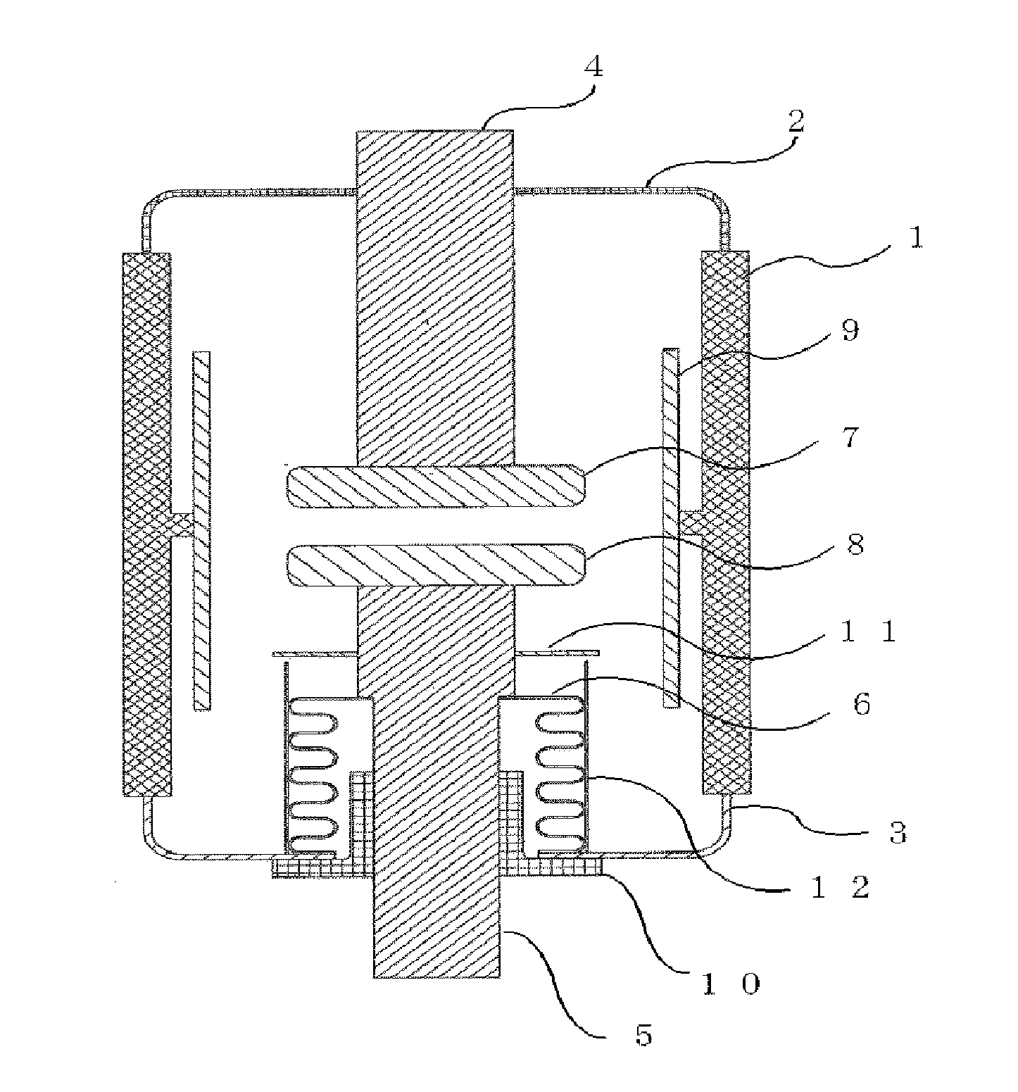
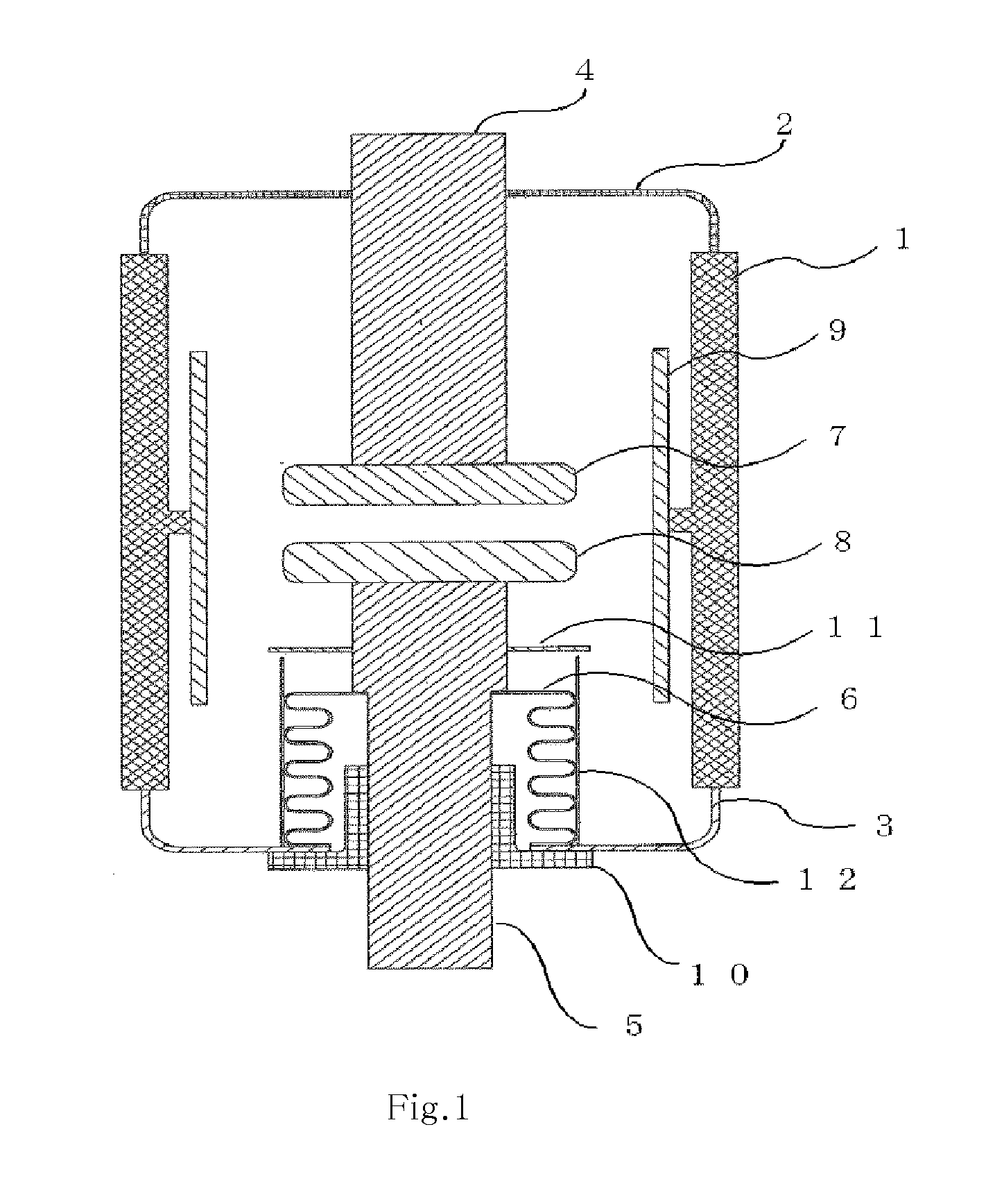
[0013]FIG. 1 is a cross-sectional view illustrating a vacuum interrupter according to Embodiment 1 of the present invention. Hereinafter, a configuration of the vacuum interrupter according to Embodiment 1 of the present invention is explained based on FIG. 1. An insulator 1 having a cylindrical shape is configured of material such as alumina ceramic. A fixed end plate 2 and a movable end plate 3 are fixed by brazing to respective both ends of the insulator 1, which constitute a vacuum vessel. Silver brazing material is mainly used for such brazing bonding.

[0014]A fixed conductor 4 penetrates through the fixed end plate 2 to be bonded by brazing. One end of a bellows 6 is bonded by brazing to the movable end plate 3, while the other end is bonded by brazing to a movable conductor 5 penetrating through the inner portion of the bellows 6 and the movable end plate 3. The side of the bellows 6 has an accordion portion where mountains and valleys are alternately formed, and thereby confi...

embodiment 2

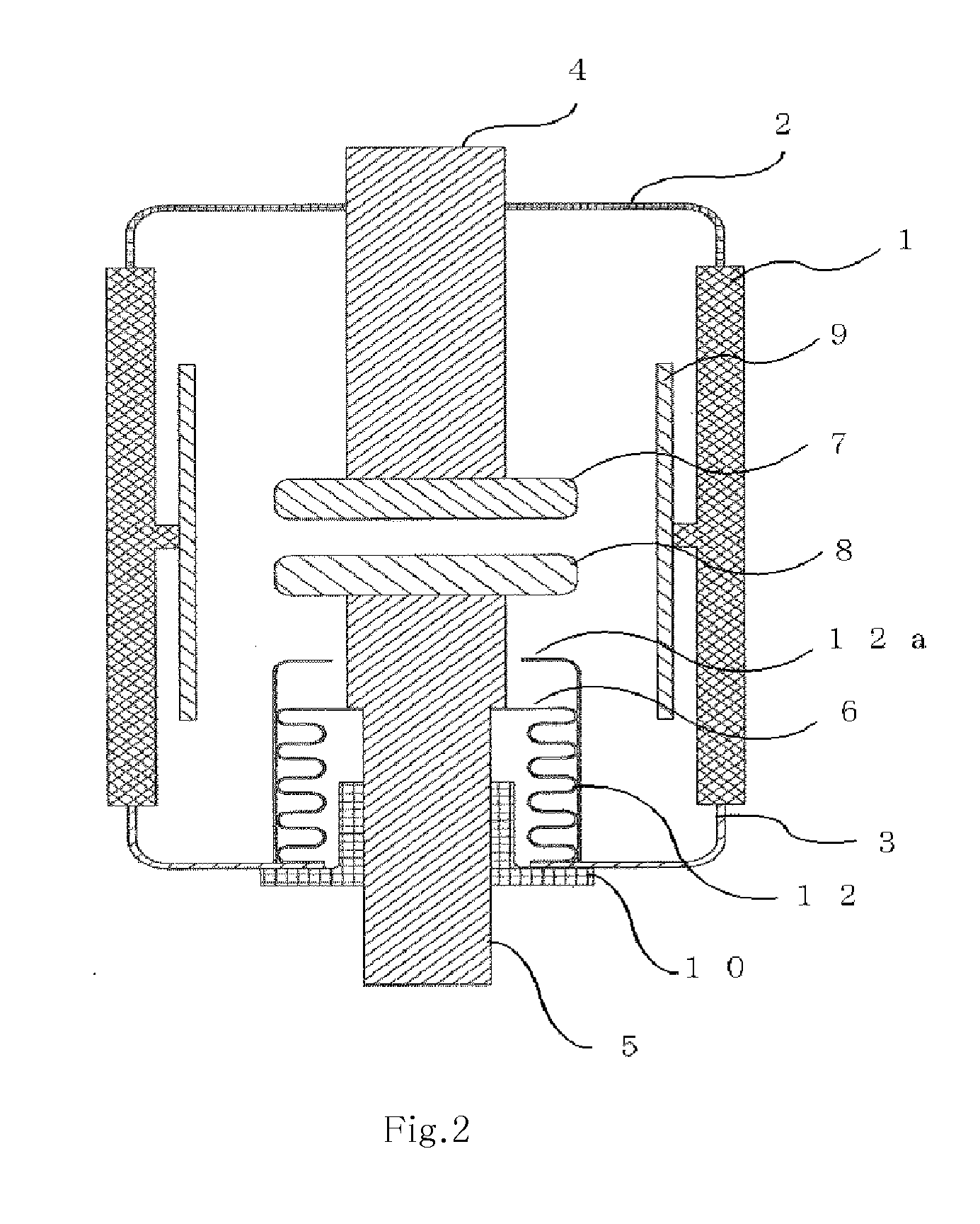
[0028]FIG. 2 is a vertical cross-sectional view illustrating a vacuum interrupter according to Embodiment 2 of the present invention. The same numerals are given to the same components as those in FIG. 1, and their explanation is omitted. Regarding also the vacuum interrupter according to Embodiment 2 of the present invention, its basic configuration is the same as that according to Embodiment 1.

[0029]The difference from the vacuum interrupter according to Embodiment 1 is that in Embodiment 2 the bellows shield 11 is removed from the vacuum interrupter in Embodiment 1, and instead a shielding portion 12a is integrally formed at an end of the bellows support member 12 on the side of the movable contact 8. The shielding portion 12a is arranged at a position, intervening between the contact side edge of the bellows 6 and the movable contact 8, where the shielding portion 12a does not contact the movable contact 8 during the open / close operation. The shielding portion 12a shields betwee...


PUM


Abstract

A vacuum interrupter includes a vacuum vessel configured with an insulator, a fixed end plate and a movable end plate fixed to both ends of the insulator. A fixed contact and a movable contact face each other inside the vacuum vessel. A movable conductor has one end fixed to the movable contact and the other end is extracted outside the vacuum vessel. A bellows has an accordion portion expanding and contracting with linear movement of the movable conductor. A bellows support member having a cylindrical shape is fixed to the vacuum vessel so that the accordion portion of the bellows contacts the inside of the bellows support member.

Description

TECHNICAL FIELD[0001]The present invention relates to a vacuum interrupter, especially to that provided with a bellows.BACKGROUND ART[0002]In a vacuum interrupter, a movable conductor is provided with a bellows, and airtightness of a vacuum vessel is maintained by expanding and contracting of the bellows with an operation of the movable conductor. The bellows is generally configured of metal such as stainless steel.[0003]Atmospheric air or pressurized insulation gas is contained inside the bellows. On the other hand, vacuum is applied to the outer side of the bellows because its outside is inside the vacuum interrupter. Thus, because the inside pressure of the bellows is higher than the outside pressure of the bellows, and both ends of the bellows are restrained, buckling in which the bellows deforms may occur when a switch opening operation of the movable conductor is performed.[0004]As a counter-measure for this problem, by increasing the outer diameter of the bellows, the bucklin...

Claims


Application Information

Patent Timeline
Patent Type & Authority Applications(United States)
IPC IPC(8): H01H33/662
CPCH01H33/66238H01H33/66261H01H3/60H01H33/66H01H33/66207
Inventor MIKI, SHINICHI
Owner MITSUBISHI ELECTRIC CORP
Why Eureka
Try Eureka