Unlock instant, AI-driven research and patent intelligence for your innovation.

Electronic Cabinet/Drawer Lock System

a cabinet/drawer lock and electronic technology, applied in the direction of building locks, construction, construction fastening devices, etc., can solve the problems of many prior art devices that cannot be easily installed to engage with the mating part located above, most devices in the prior art cannot communicate with the centrally located access control system in wireless mode, and none of the prior art units have the capability of delaying the unlock signal

Active Publication Date: 2013-03-21
HANCHETT ENTRY SYST
View PDF26 Cites 64 Cited by
  • Summary
  • Abstract
  • Description
  • Claims
  • Application Information

AI Technical Summary

Benefits of technology

The invention is a wireless battery-operated locking system for cabinet / locker doors or drawers. It consists of an external assembly and an internal assembly. The external assembly includes a cover housing, a knob, a card / credential reader, a status indicator, a wireless communication capability, a wire harness, and a jump port plug and cap. The internal assembly includes a housing, a shaft rotation link, a latch bolt assembly, a battery-powered circuit board and controller, a battery-powered locking and unlocking mechanism, a mechanical key override feature, a unit locked sensing feature, a preload sensing feature, and a battery. The battery-powered locking mechanism includes a gear set linking the shaft rotation link with the latch sleeve and a battery-powered motor that can move the blocker inhibiting motion of the latch bolt. The system allows for wireless authorization and locking and unlocking through the knob and shaft rotation link.

Problems solved by technology

In either embodiment, the latching mechanism is actuated by a linear solenoid or small DC motor powered by an external DC supply, which is difficult for either a door-latching or drawer-latching application wherein the locking mechanism is mounted on the movable member.
Many prior art devices cannot easily be installed to engage with a mating part located above or to the side of the movable member.
Most devices in the prior art cannot communicate with a centrally located access control system in a wireless mode.
None of the prior art units have the capability of delaying the unlock signal until any preload on the release mechanism has been removed.
Also, none of the prior art devices have the ability to sense the presence of the locking member in its mating part which is mounted in the top or side wall of the cabinet.
Finally, few if any prior art devices have a mechanical key override.

Method used


Image

  • Electronic Cabinet/Drawer Lock System
  • Electronic Cabinet/Drawer Lock System
  • Electronic Cabinet/Drawer Lock System

Examples


Embodiment Construction

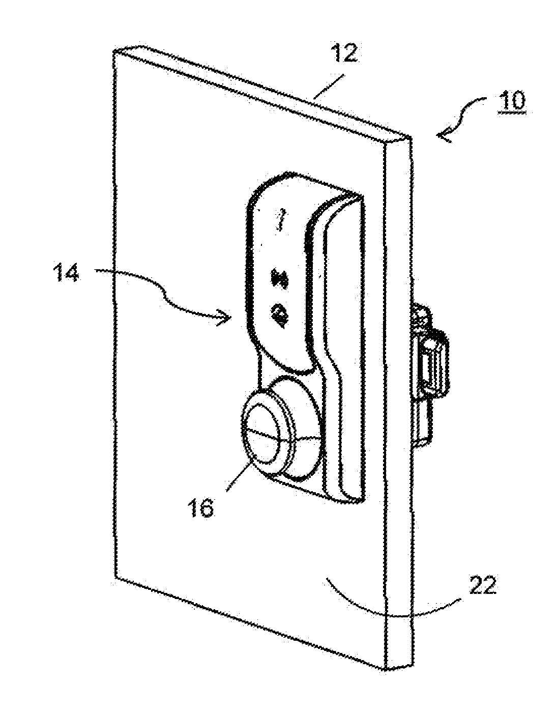
[0027]There exists the need for a wireless battery operated locking system that has a spring latch mechanism which automatically locks a cabinet / locker door or drawer when pushed closed. The system must also be able to change to an unlocked state when the system's card reader is presented with valid credentials. Additionally, the system must support being surface-mounted on either a cabinet / locker door or a drawer front face, configured in any of four positions. These positions are in axial rotation about the knob with minimum intervals of 90°, as shown and described more fully below in FIGS. 6 through 8.

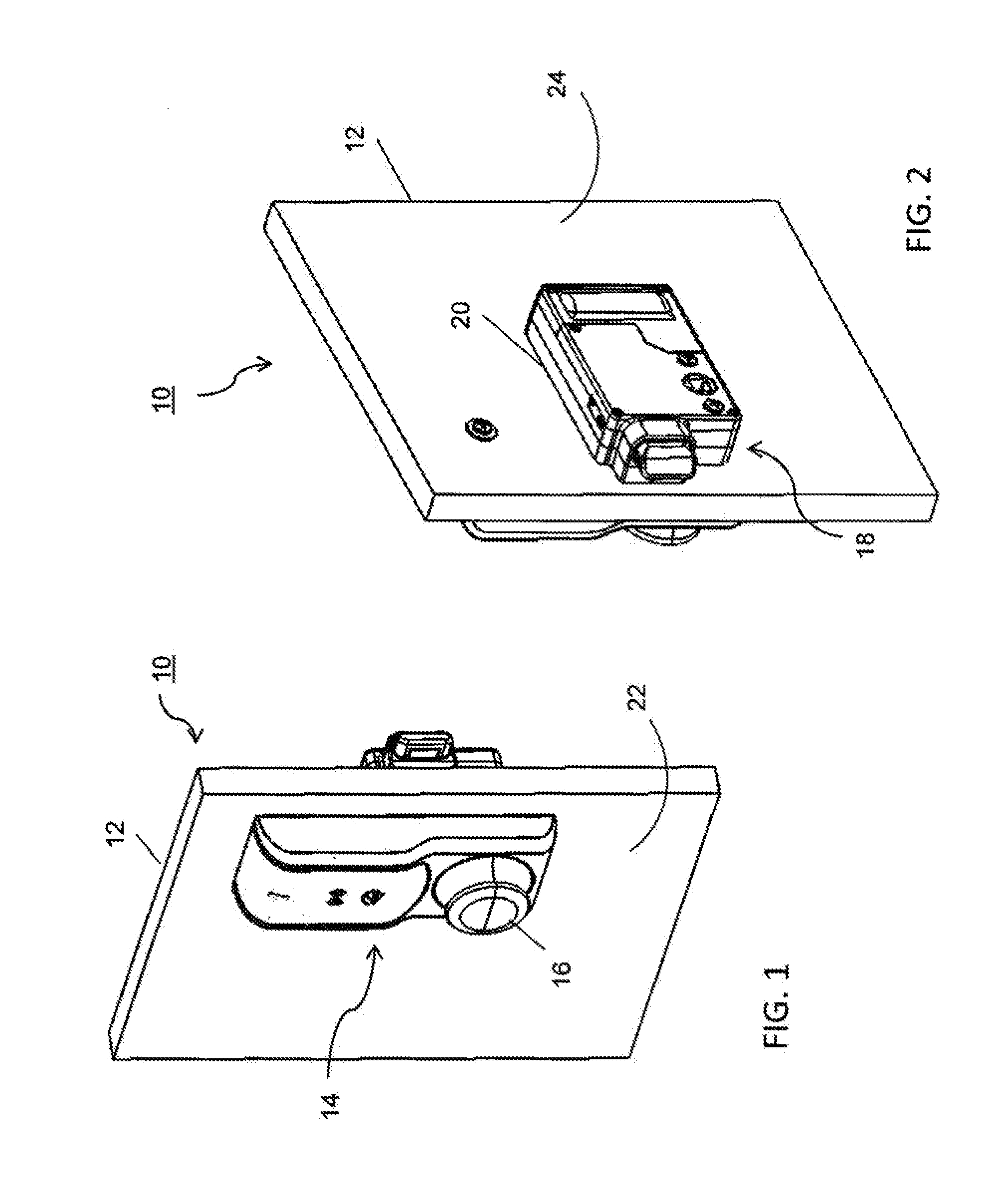
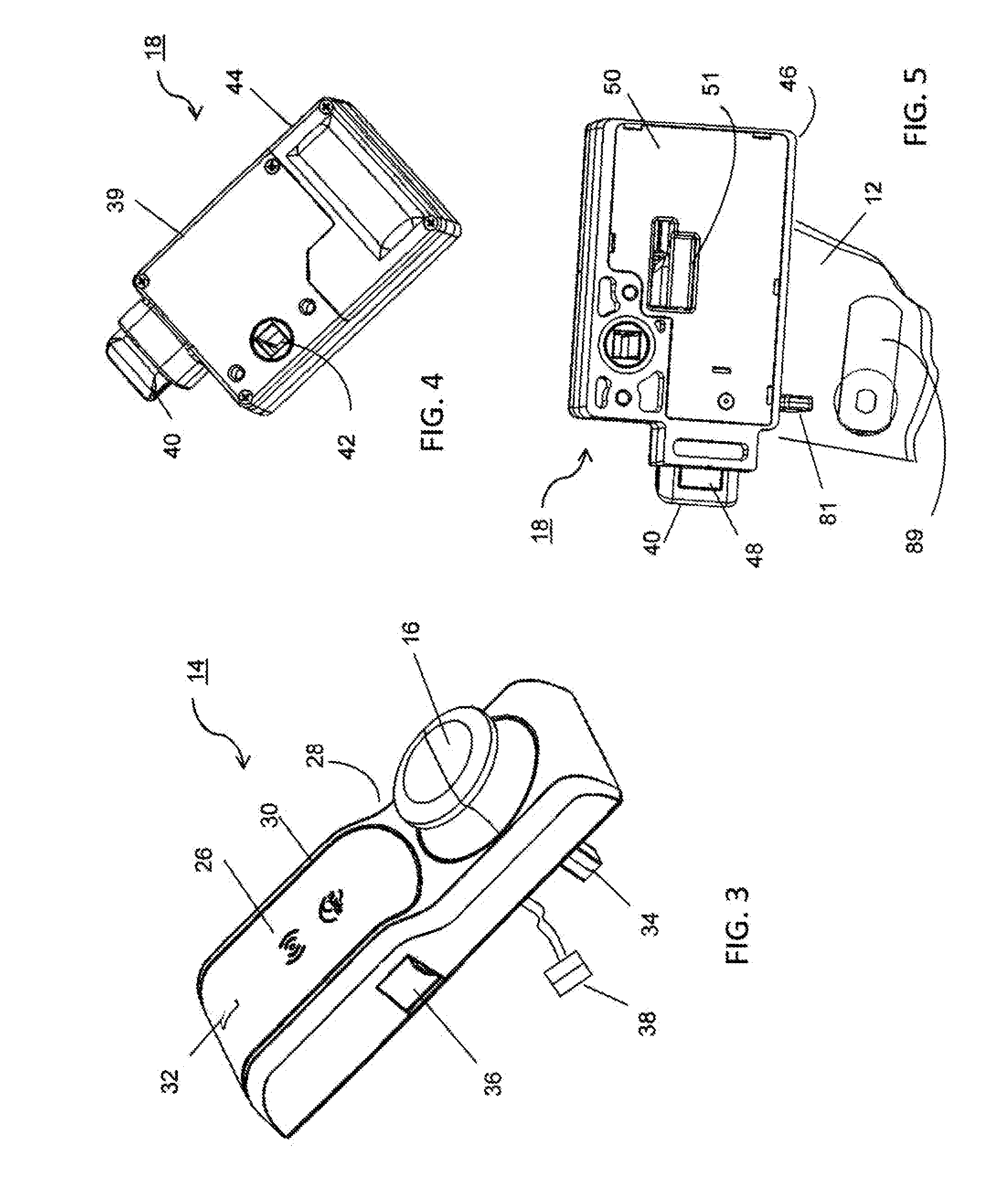
[0028]Referring to FIGS. 1 through 5, a general layout is shown for a wireless battery operated locking system 10 for locking a cabinet or locker door or drawer 12 (all referred to herein below as “cabinet door”) in accordance with the present invention.

[0029]System 10 includes external assembly 14, including a rotatable knob 16 and internal assembly 18 including a battery-operated ...


PUM


Abstract

An electronic wireless locking system comprising an external assembly and an internal assembly disposable on respective sides of a door or drawer. The external assembly includes a cover housing, a knob having a shaft, a card / credential reader, a status indicator, a wireless communication capability, a wire harness and a jump port plug. The internal assembly comprises a rotation link matable with the external shaft, a latch bolt, a circuit board and controller, and a locking mechanism including a rack and pinion gear set linking the rotation link with the latch bolt. A blocker inhibits the latch bolt from unlocking until authorized to rotate 90°, permitting the latch bolt to be withdrawn from a strike plate by manual rotation of the knob. An optional mechanical key override feature may also be provided. The system may further include a preload sensor and a device locked sensor.

Description

[0001]This Application claims the benefit of U.S. Provisional Application No. 61 / 536,013, filed Sep. 18, 2011.TECHNICAL FIELD[0002]The present invention relates to electronically-controlled lock systems, and also to cabinet latches; more particularly, to a system for securely latching a cabinet / locker door or drawer with an electronic lock mechanism; and most particularly, to a battery-powered electronic lock system responsive to a card reader or other authorization means, suitable for securely latching of a cabinet / locker door or drawer.BACKGROUND OF THE INVENTION[0003]Locking systems for securing cabinet / locker doors and drawers are well known in the prior art. Typically, such a system may comprise a simple spring latch actuated by manual turning of a key in an associated barrel lock.[0004]More sophisticated door locking security systems are known wherein an electro-mechanical latching apparatus may be actuated by a card reader or key pad. The electromechanical mechanism is known ...

Claims


Application Information

Patent Timeline
IPC IPC(8): E05B47/00E05B65/52
CPCE05B65/52E05B47/00E05B63/006E05C1/16E05B2047/0058E05B2047/0094Y10T70/5097E05B47/0607
Inventor WEBB, MICHAEL A.SULLIVAN, SCOTT P.FIGUEROA-DEL POZO, FRANCISCOWILDING, ANDREW LEEPEABODY, JOSHUA T.SCHEFFLER, DOMINIK
Owner HANCHETT ENTRY SYST