
Automatic placement of precision cuts

a technology of precision cutting and automatic placement, applied in the field of orthodontics, can solve the problems of little room for bonding such brackets to patients' teeth, and difficulty in generating such a tension force in conjunction with recently developed orthodontic approaches

Active Publication Date: 2013-04-11
ALIGN TECH +1
View PDF9 Cites 153 Cited by
  • Summary
  • Abstract
  • Description
  • Claims
  • Application Information

AI Technical Summary

Benefits of technology

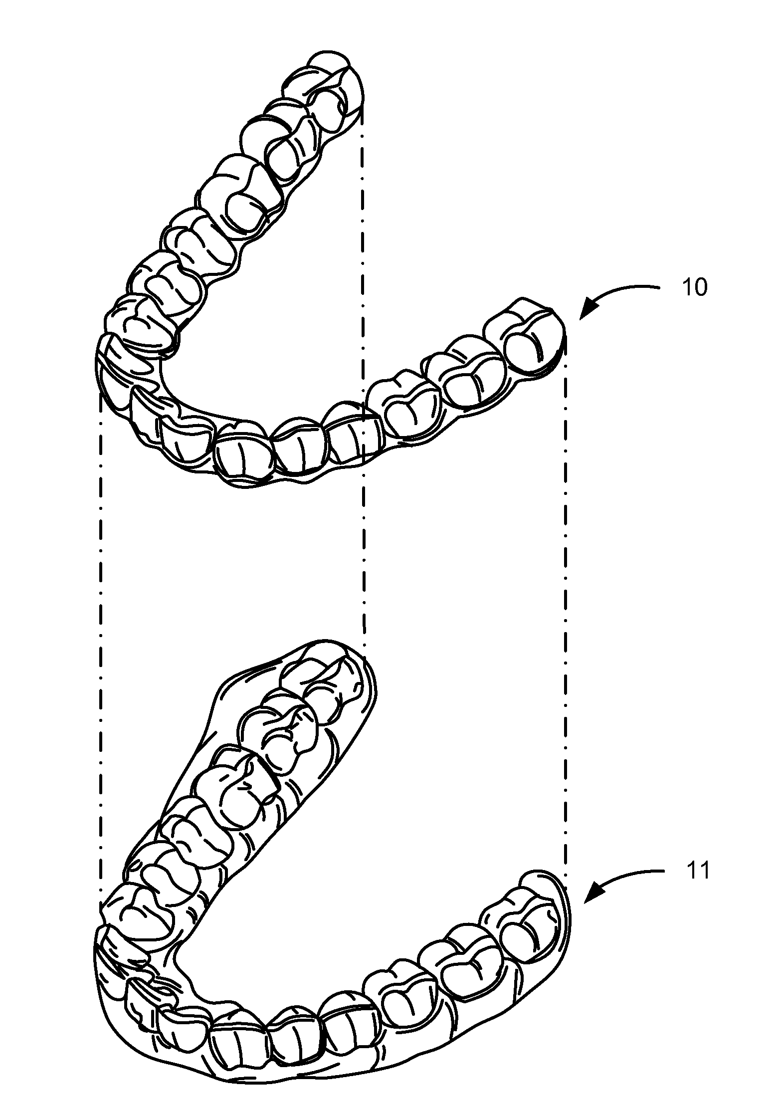
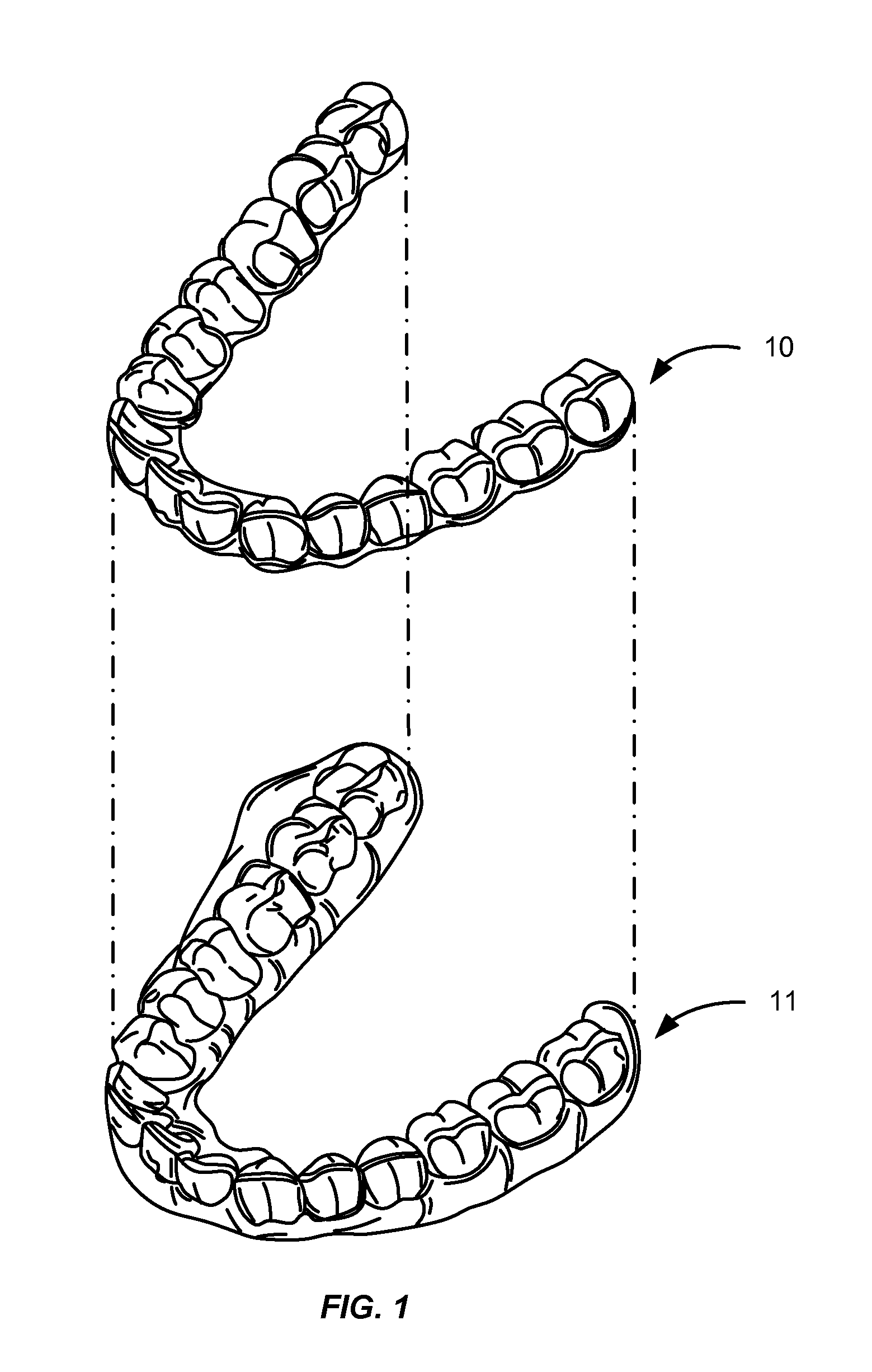
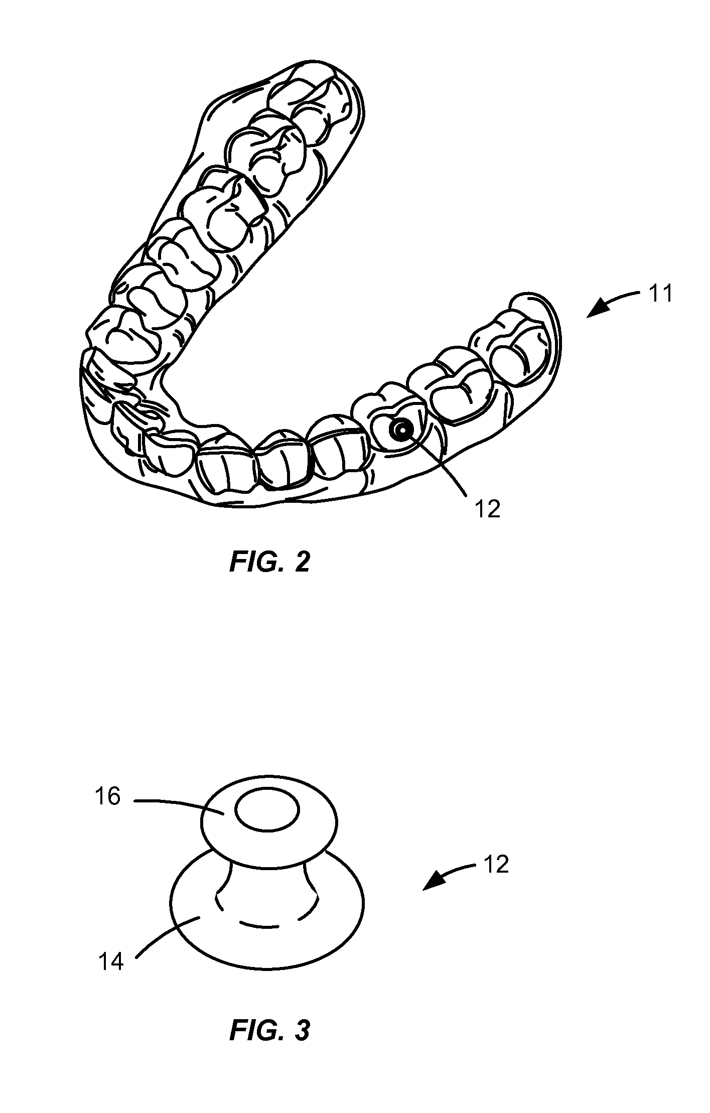
This patent describes an orthodontic system that uses positioning appliances and an elastic band to move a patient's teeth. The appliances are made to fit over the patient's teeth and apply a gentle force to move them in the desired position. This system helps align the patient's teeth and improve the overall appearance of the smile. The technical effects of this patent include improved orthodontic treatment outcomes and more efficient use of orthodontic elastic bands.

Problems solved by technology

Generating such a tension force in conjunction with recently developed orthodontic approaches can be challenging.
For example, shell aligners are often designed to match the geometry of a patient's teeth, thereby leaving little room for bonding such brackets to a patient's teeth.

Method used


Image

  • Automatic placement of precision cuts
  • Automatic placement of precision cuts
  • Automatic placement of precision cuts

Examples


first embodiment

[0138]Turning back to FIG. 12, in operation 178, the hook cutout line may be extended from the point on the tooth outside the gingival line to a second point on the gingival line of the tooth. In extending the hook cutout line back to the gingival line, the entire hook may be defined. For example, FIG. 13G shows a simplified digital representation 240 of a patient's tooth 102 and an extended cutout line 182 according to a Extended cutout line 182 includes an extension from point Ito a point K on gingival line 108. In this case, the extension passes through an additional point J.

second embodiment

[0139]The extension from point Ito point K may have any suitable shape and length. In one embodiment, as shown in FIG. 13G, the extension includes a first portion extending between points I and J and a second portion extending between points J and K. Further, the second portion extending between points J and K is in parallel with the portion extending between points H and I, and is provided at a distance from the portion extending between points H and I based on slit offset L (FIG. 13C). In this embodiment, the portion extending from point Ito point J is linear. However, this portion may assume one or more curves. For example, FIG. 13H shows a simplified digital representation 250 of a patient's tooth 102 and an extended cutout line 182 according to a In this case, the portion extending between points I and J is a curved line rather than a straight line.

[0140]Once the hook cutout line has been generated, the cutout line may be used to fabricate an orthodontic tooth positioning appl...


PUM


Abstract

An orthodontic positioning device and methods for making an orthodontic positioning device including a first patient removable orthodontic tooth positioning appliance having teeth receiving cavities shaped to receive and apply a resilient positioning force to a patient's teeth provided in one of an upper jaw and a lower jaw. The first appliance includes a hook configured to receive an orthodontic elastic band. The orthodontic positioning device also includes a second patient removable orthodontic tooth positioning appliance having teeth receiving cavities shaped to receive and apply a resilient positioning force to a patient's teeth provided in the other of the upper jaw and the lower jaw. The second appliance includes a cutout operable to expose an orthodontic elastic band receiving member.

Description

BACKGROUND[0001]The present invention generally relates to the field of orthodontics, and more particularly to the design of dental positioning appliances precisely configured to interface with an orthodontic elastic member.[0002]An objective of orthodontics is to move a patient's teeth to positions where function and / or aesthetics are optimized. Traditionally, appliances such as braces are applied to a patient's teeth by a treating practitioner and the set of braces exerts continual force on the teeth and gradually urges them toward their intended positions. Over time and with a series of clinical visits and adjustments to the braces, the practitioner adjusts the appliances to move the teeth toward their final destination.[0003]More recently, alternatives to conventional orthodontic treatment with traditional affixed appliances (e.g., braces) have become available. For example, systems including a series of preformed appliances / aligners have become commercially available from Align...

Claims


Application Information

Patent Timeline
IPC IPC(8): A61C7/08A61C7/00
CPCA61C7/08A61C7/36A61C7/002B33Y80/00A61C19/05A61C2007/004
Inventor BOROVINSKIH, ARTEMTEREKHOV, ANTONSTERENTAL, RENEMINCHENKOV, MIKHAILPAVLOV, IVAN
Owner ALIGN TECH
Learn More