Lens cleaner and optical disc device

a technology of optical discs and cleaners, applied in the field of optical disc cleaners, can solve the problems of difficult recording or reproduction of information on or from optical discs b>100/b>, and achieve the effect of cleaning grime o

Active Publication Date: 2013-06-06
PANASONIC CORP
View PDF0 Cites 9 Cited by
  • Summary
  • Abstract
  • Description
  • Claims
  • Application Information

AI Technical Summary

Benefits of technology

[0039]Since the lens cleaner of the present invention comprises the first and second lens cleaning portions, it becomes possible to more surely clean the grime off from the objective lens.

Problems solved by technology

This makes it difficult for recording or reproduction of information on or from the optical disc 100 to be achieved.

Method used


Image

  • Lens cleaner and optical disc device
  • Lens cleaner and optical disc device
  • Lens cleaner and optical disc device

Examples


first embodiment

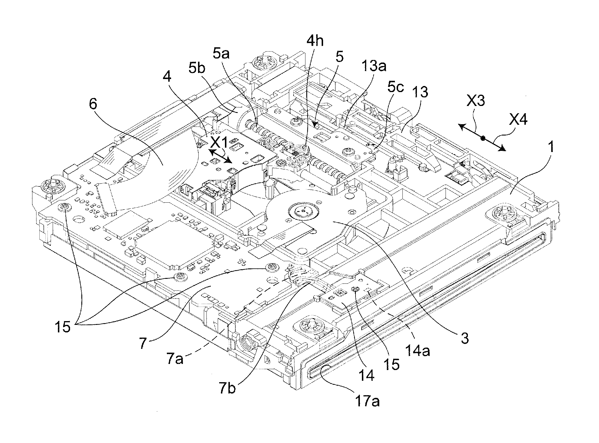
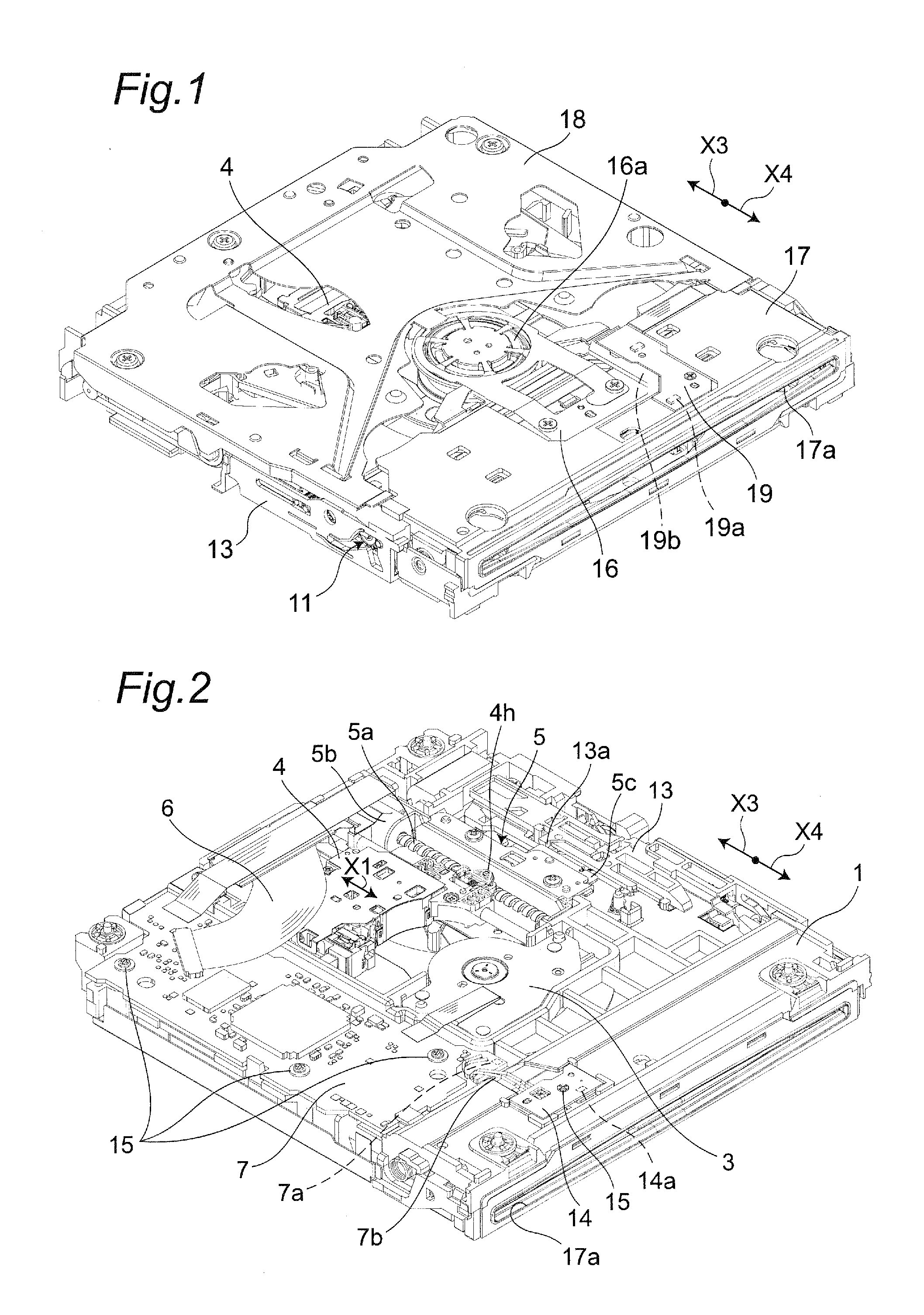
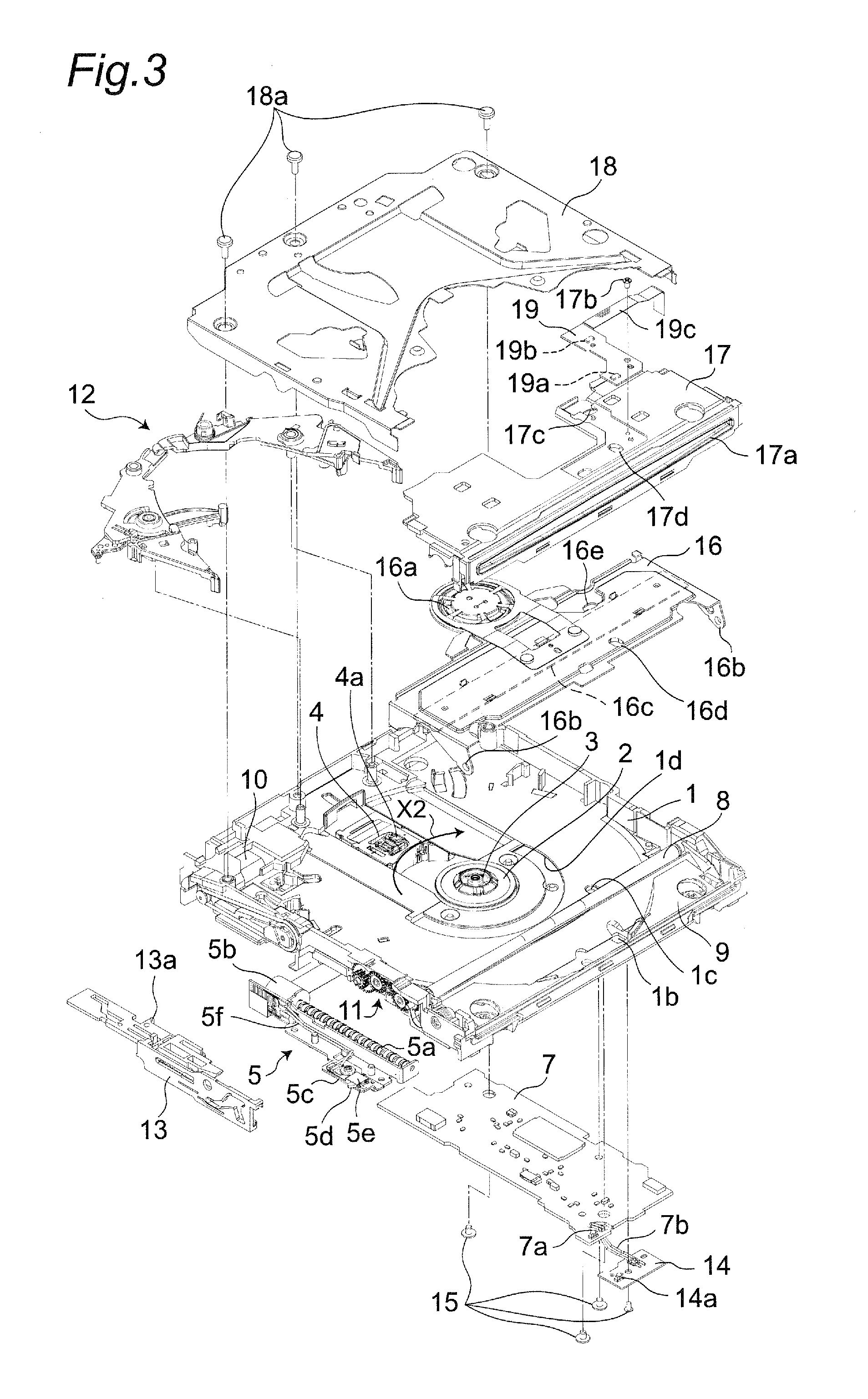
[0064]With reference to FIGS. 1 to 4, a description will be given of the overall structure of an optical disc device according to a first embodiment of the present invention. FIG. 1 is a perspective view of the optical disc device according to the first embodiment of the present invention as seen from diagonally above. FIG. 2 is a perspective view of the optical disc device as seen from diagonally below. FIG. 3 is an exploded perspective view of the optical disc device according to the first embodiment of the present invention. FIG. 4 is a partial enlarged schematic cross-sectional view of the optical disc device according to the first embodiment of the present invention when recording on or reproducing from an optical disc. It is noted that, for the sake of convenience, the description will proceed based on the premise that the top side of FIG. 1 is the top side of the optical disc device and the bottom side of FIG. 1 is the bottom side of the optical disc device. However, the pres...

second embodiment

[0115]With reference to FIGS. 17 and 18, a description will be given of a lens cleaner according to a second embodiment of the present invention. FIG. 17 is a perspective view of the lens cleaner, and FIG. 18 is a plan view of the lens cleaner.

[0116]A lens cleaner 20A according to the second embodiment is different from the lens cleaner 20 according to the first embodiment in that the first and second lens cleaning portions 21A and 22A are each structured by two different cleaning members 21a, 21b, 22a, and 22b. The cleaning members 21a to 22b are arranged in parallel with the rotation direction X2. Further, the cleaning member 21a and the cleaning member 21b are arranged so as to have a slight distance D1 (e.g., 1 mm) between each other. Similarly, the cleaning member 22a and the cleaning member 22b are arranged so as to have a slight distance D1 between each other.

[0117]In order to effectively clean grime off from the objective lens 4a, it is effective to employ a soft nonwoven fa...

third embodiment

[0122]A description will be given of the structure of an optical disc device according to a third embodiment of the present invention. The optical disc device according to the third embodiment is different from the optical disc device according to the first embodiment in that: light is emitted from the objective lens 4a to the lens cleaner 20; a change in the distance between the objective lens 4a and the lens cleaner 20 is sensed based on a change in the intensity of the reflected light, and the rotation speed of the turntable 2 is controlled based on the change in the distance. It is noted that the control is exerted by an electronic component such as an LSI that is installed in the drive substrate 7 and that functions as the controller.

[0123]The vibration frequency and amplitude of the objective lens 4a when the objective lens 4a is brought into contact with the first lens cleaning portion 21A may vary attributed to the diameter or length of the suspension wires 4c, or changes ov...


PUM

PropertyMeasurementUnit
diameteraaaaaaaaaa
diameteraaaaaaaaaa
radius R1aaaaaaaaaa

Abstract

A lens cleaner capable of more surely cleaning grime off from an objective lens is provided. A lens cleaner of the present invention includes first and second lens cleaning portions. The first lens cleaning portion is provided to be brought into contact with a lens protector when the lens cleaner is rotated, to cause an objective lens to be away from a recording or reproducing position against an elastic force of an elastic member. The second lens cleaning portion is provided on an upstream side in a rotation direction relative to the first lens cleaning portion. The second lens cleaning portion is provided to pass above the lens protector while the objective lens is away from the recording or reproducing position, and to be brought into contact with the objective lens when the objective lens returns to the recording or reproducing position by the elastic force of the elastic member.

Description

BACKGROUND OF THE INVENTION[0001]The present invention relates to an optical disc device that performs recording or reproduction of information on or from an optical disc such as a CD (compact disc), a DVD (digital versatile disc), or the like. In particular, the present invention relates to a lens cleaner that cleans an objective lens of an optical head included in such an optical disc device.[0002]Conventionally, an optical disc device of this kind has the structure such as shown in FIGS. 19 and 20. FIG. 19 is a partial enlarged perspective view showing the structure of a conventional optical disc device. FIG. 20 is a partial enlarged schematic cross-sectional view of the conventional optical disc device in an optical disc recording or reproducing mode.[0003]The conventional optical disc device includes a chassis 101 that retains components. The chassis 101 is provided with a spindle motor 103 that rotates a turntable 102 to which an optical disc 100 is attached, and an optical he...

Claims


Application Information

Patent Timeline
Patent Type & Authority Applications(United States)
IPC IPC(8): G11B33/14
CPCG11B7/121G11B33/1446
Inventor MATSUMURA, ASAYUKIWADA, TAKUYA
Owner PANASONIC CORP
Why Eureka
Try Eureka