Ignition system

a technology of ignition system and spark plug, which is applied in the direction of spark plugs, machines/engines, mechanical equipment, etc., can solve the problems of high discharge voltage of spark plugs, no discharge sparks, and impair the reliability of spark plugs

Active Publication Date: 2013-08-08
DENSO CORP
View PDF24 Cites 10 Cited by
  • Summary
  • Abstract
  • Description
  • Claims
  • Application Information

AI Technical Summary

Benefits of technology

[0018]Specifically, at least either of the number of turns of the primary coil and the stray capacitance of the spark plug is configured such that, under the conditions where voltage applied to the gap is increasing after current supply to the primary coil has been cut off to achieve the variation range equal to or smaller than the predetermined time, time (rise time) will be shortened from when the voltage applied to the gap reaches a first predetermined voltage until when it reaches a second predetermined voltage which is higher than the first predetermined voltage. With this adjustment, when deterioration of the spark plug is advanced, the actual timing of producing discharge sparks is prevented from being excessively delayed from an appropriate timing of producing discharge sparks.
[0019]According to the fourth to sixth aspects set forth above, timing of producing discharge sparks can be prevented from being excessively delayed from an appropriate timing of producing discharge sparks, under the conditions where deterioration of the spark plug is advanced. Further, the combustion conditions in the internal combustion engine are hardly worsened.

Problems solved by technology

Thus, the spark plug will have high discharge voltage.
When the discharge voltage becomes high under the conditions where the electrodes' wear in the spark plug is advanced due to the increase of a running distance or the like, the discharge voltage may exceed an insulation-breakdown limit voltage of a plug insulator at an early stage, impairing reliability of the spark plug.
As a result, discharge sparks would no longer be produced, which may lead to the occurrence of an accidental fire in the internal combustion engine.
The discharge voltage of a spark plug tends to become higher not only by the in-cylinder pressure but also by age-related deterioration of the spark plug.
An excessively high discharge voltage due to age-related deterioration may impair reliability of the spark plug and thus may no longer allow discharge sparks to be produced in the gap.

Method used


Image

  • Ignition system
  • Ignition system
  • Ignition system

Examples


first embodiment

[0034]With reference to the accompanying drawings, hereinafter are described some embodiments of the present invention. Referring to FIGS. 1 to 4 and FIGS. 5A and 58 first, a first embodiment of the present invention is described, in which an ignition system according to the present invention is applied to an on-vehicle spark-ignition engine.

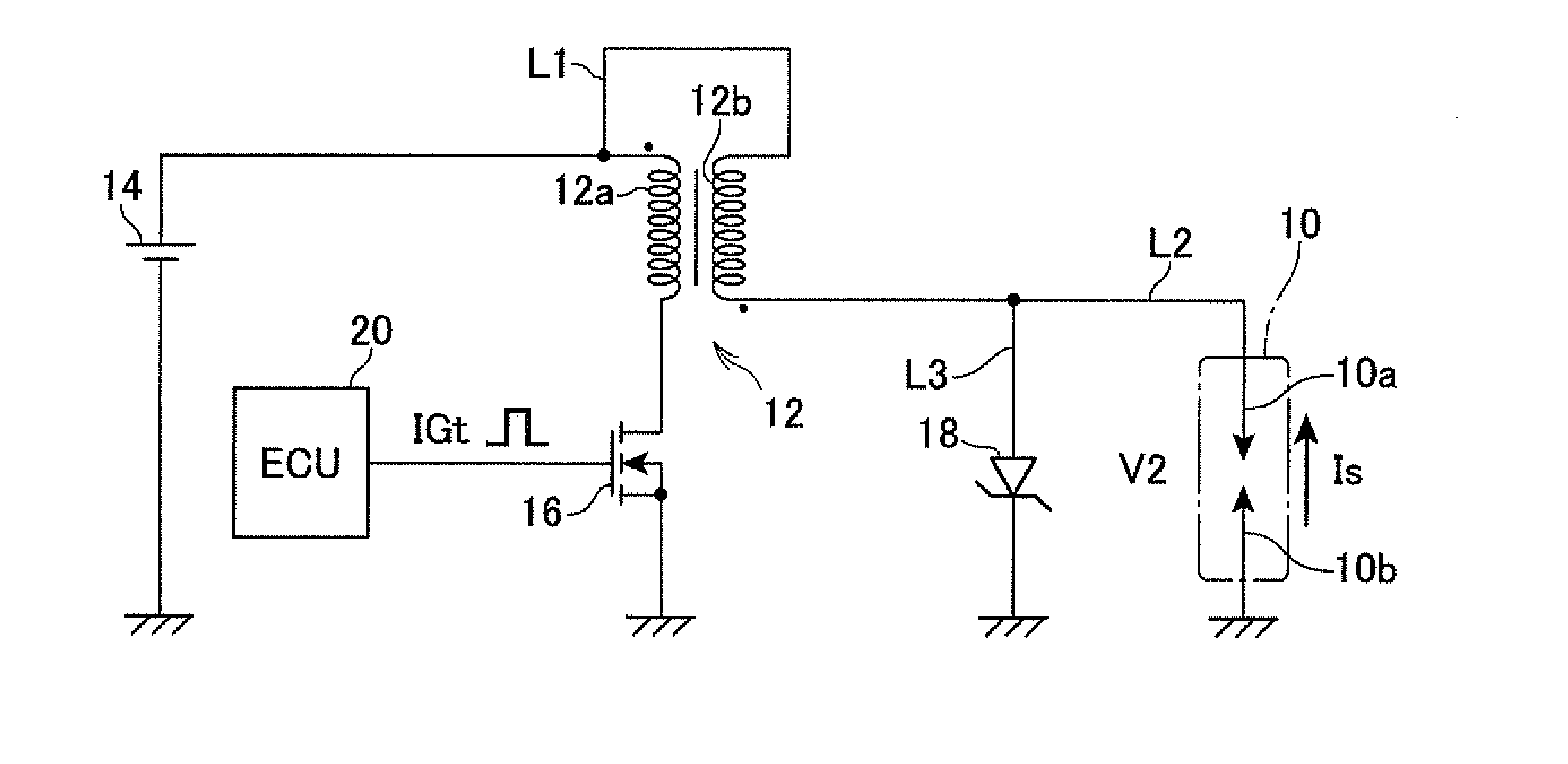
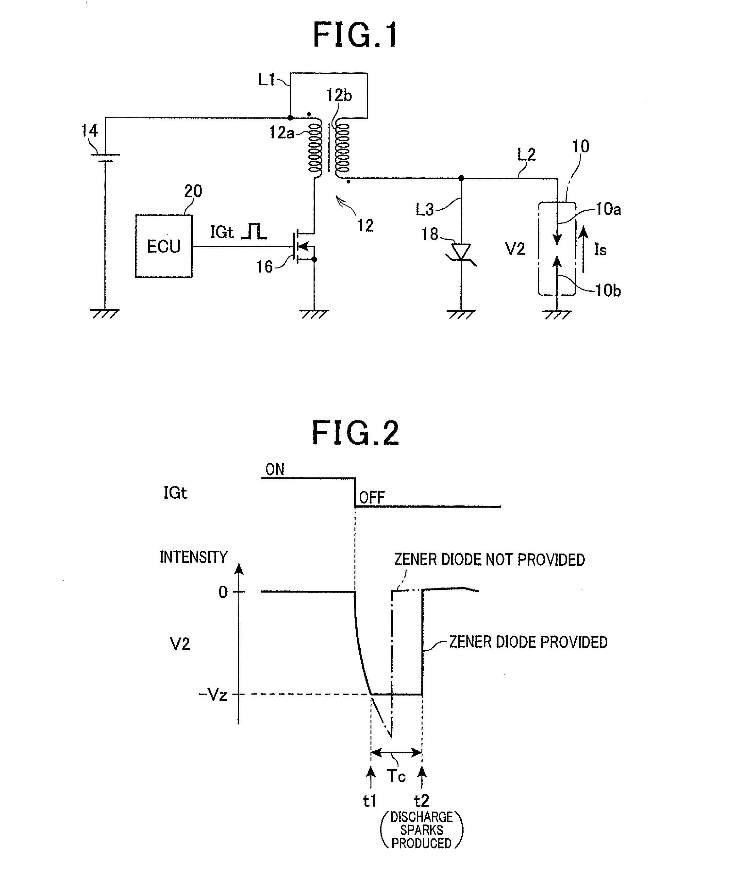
[0035]FIG. 1 is a schematic diagram generally illustrating the ignition system according to the first embodiment.

[0036]As shown in FIG. 1, the ignition system includes a spark plug 10 and a spark coil (ignition coil) 12. The spark plug 10 is composed of a center electrode 10a and a ground electrode 10b and has a function of producing discharge sparks in a combustion chamber of an engine, not shown.

[0037]The spark coil 12 is composed of a primary coil 12a and a secondary coil 12b magnetically connected to the primary coil 12a. The secondary coil 12b has ends, one of which is connected to a positive side (corresponding to a member having a referen...

second embodiment

[0068]Referring now to FIGS. 6A to 6E and FIGS. 7 to 10, hereinafter is described an ignition system according to a second embodiment of the present invention focusing on differences from the first embodiment. In the second embodiment, the components identical with or similar to those in the first embodiment are given the same reference numerals for the sake of omitting unnecessary explanation.

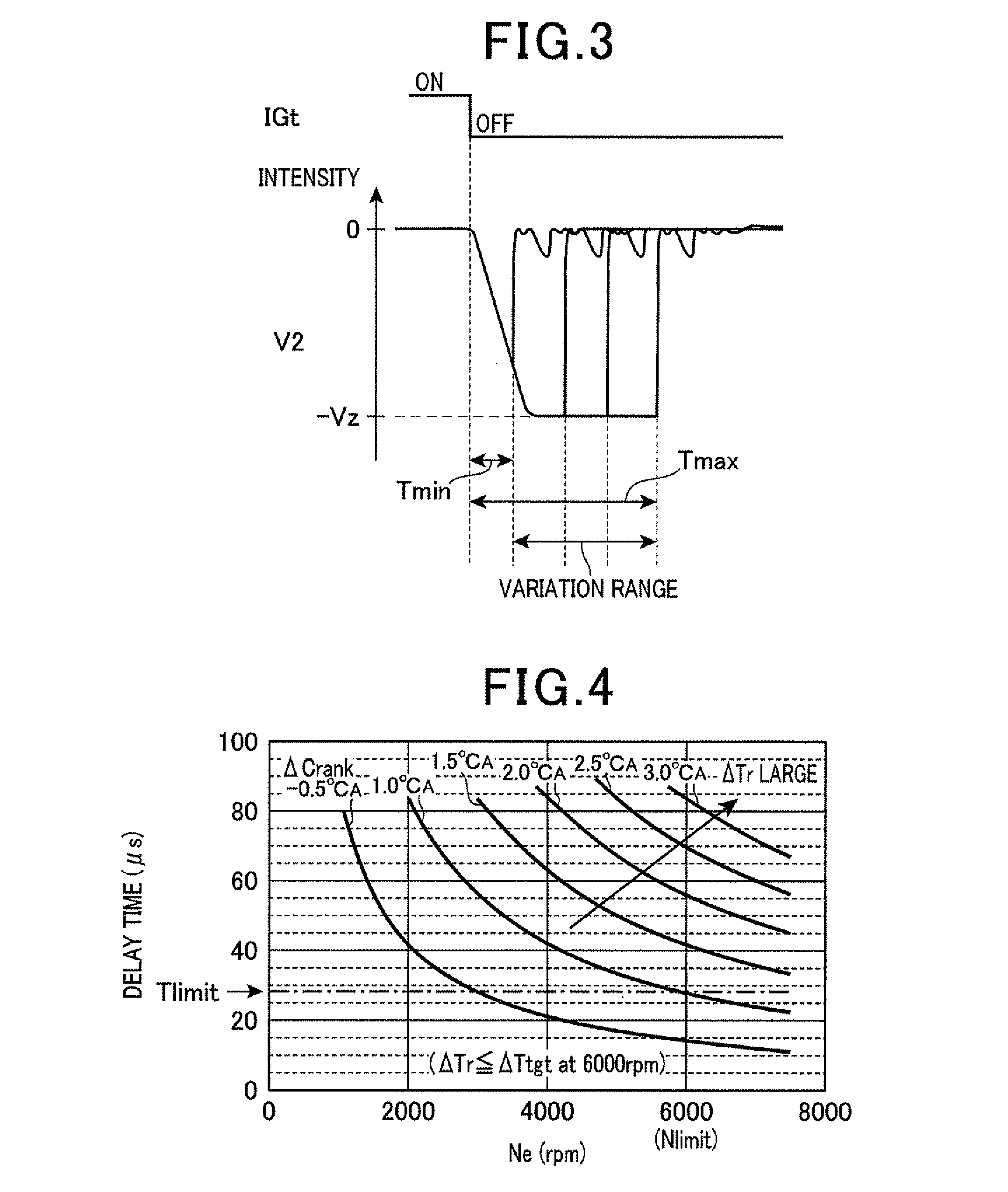
[0069]The ignition system according to the second embodiment is different from the first embodiment in the configuration for achieving the variation range equal to or smaller than the predetermined time Tlimit. Specifically, the ignition system is configured to shorten a rise time so that the variation range is rendered to be the predetermined time Tlimit or smaller. In the present embodiment, the rise time refers to a time from when the secondary voltage V2 has reached a first predetermined voltage Vf1 until when it reaches a second predetermined voltage Vf2, under the conditions where the on...


PUM


Abstract

An ignition system is provided, in which a Zener diode is connected in parallel with a spark plug, to suppress torque variation from becoming large in an engine when deterioration of the spark plug is advanced. Specifically, the ignition system includes a secondary coil having an end connected to a center electrode of the spark plug via a connecting path. The connecting path is connected to a constant-voltage path having a grounded end and including the Zener diode. The time from when an ignition signal is switched off until when ignition timing occurs is measured for a plurality of times. The difference between a maximum value and a minimum value among the plurality of measurements is defined to be a variation range. A breakdown voltage of the Zener diode is adjusted based on requirements such as for rendering the variation range to be a predetermined time or smaller.

Description

CROSS-REFERENCE TO RELATED APPLICATION[0001]This application is based on and claims the benefit of priorities from earlier Japanese Patent Application Nos. 2012-025107 and 2012-204904 filed Feb. 8 and Sep. 18, 2012, respectively, the descriptions of which are incorporated herein by reference.BACKGROUND OF THE INVENTION[0002]1. Technical Field of the Invention[0003]The present invention relates to an ignition system that includes a spark coil having a primary coil and a secondary coil magnetically connected to each other, a spark plug having a center electrode projected into a combustion chamber of an internal combustion engine and a ground electrode, and an ignition control means for applying a high voltage to a gap between the center electrode and the ground electrode with a current supply to the primary coil and with the subsequent cutoff of the current supply, for the production of discharge sparks in the gap.[0004]2. Related Art[0005]Due to the recent trend of downsizing a spark...

Claims


Application Information

Patent Timeline
Patent Type & Authority Applications(United States)
IPC IPC(8): F02P1/08
CPCF02P3/0442F02P1/083H01T13/44F02P3/02F02P3/0552F02P3/0407
Inventor SHIBATA, MASAMICHIMIZUTANI, ATSUYAHATTORI, KOICHIIMANAKA, YASUOMI
Owner DENSO CORP
Why Eureka
Try Eureka