
Flat nonaqueous secondary battery

a secondary battery and non-aqueous technology, applied in the manufacture of final products, cell components, cell component details, etc., can solve the problems of reducing capacity, impairing battery reliability, and the corner of the positive electrode compound layer to chip off, so as to achieve the effect of improving reliability

Active Publication Date: 2014-08-12
MAXELL HLDG LTD
View PDF9 Cites 2 Cited by
  • Summary
  • Abstract
  • Description
  • Claims
  • Application Information

AI Technical Summary

Benefits of technology

[0005]If such a separator bag is formed by laying two separators upon each other to sandwich a positive electrode and then join the peripheries of these separators together using pressing or hot pressing, a corner of an end of the positive electrode (i.e. a corner of an end of a positive electrode compound layer) abuts the inner surface of a separator. This may cause a bruise on the separator or cause the corner of the positive electrode compound layer to chip off. Such problems may cause an interior short circuit or decreased capacity of the battery, impairing the reliability of the battery. As such, in a flat nonaqueous secondary battery having such a separator bag, there is a need for minimizing such problems.
[0006]The present invention was made in view of the above circumstances. An object of the present invention is to provide a flat nonaqueous secondary battery with improved reliability.
[0009]An embodiment of the present invention provides a flat nonaqueous secondary battery with improved reliability.

Problems solved by technology

This may cause a bruise on the separator or cause the corner of the positive electrode compound layer to chip off.
Such problems may cause an interior short circuit or decreased capacity of the battery, impairing the reliability of the battery.

Method used


Image

  • Flat nonaqueous secondary battery
  • Flat nonaqueous secondary battery
  • Flat nonaqueous secondary battery

Examples


Embodiment Construction

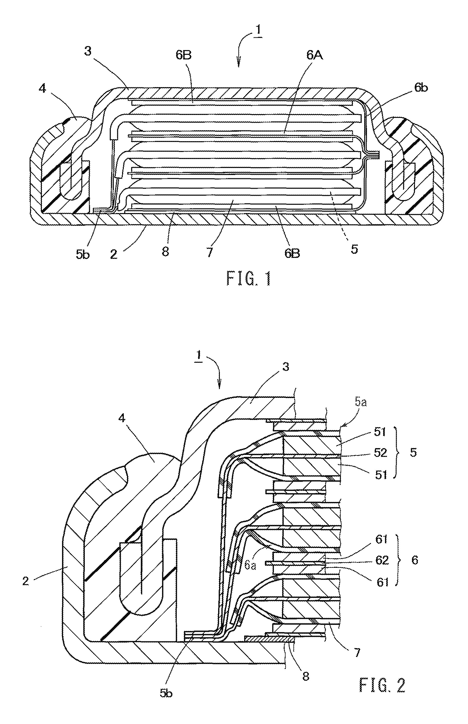
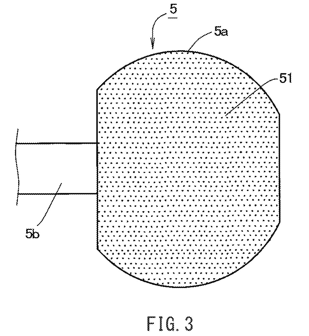
[0019]FIGS. 1 and 2 schematically show an example of a flat nonaqueous secondary battery according to an embodiment of the present invention. FIG. 1 is a vertical cross-sectional view of a battery case (consisting of an exterior case 2 and seal case 3) of the flat nonaqueous secondary battery 1 (hereinafter also referred to as “battery”) and an insulating gasket 4. FIG. 2 is an enlarged view of a portion from FIG. 1 and is a cross section of the electrode assembly. As shown in FIGS. 1 and 2, the flat nonaqueous secondary battery 1 includes an assembly of stacked electrodes, in which positive electrodes 5 and negative electrodes 6 are stacked upon each other such that their planes are generally parallel (including parallel) to the flat plane of the battery (i.e. the top or bottom surface in FIG. 1), and nonaqueous electrolyte (not shown) contained in a space (enclosed space) formed by the exterior case 2, seal case 3 and insulating gasket 4.

[0020]The seal case 3 fits within the openi...


PUM

PropertyMeasurementUnit
temperatureaaaaaaaaaa
stress concentrationaaaaaaaaaa
inner angle C2aaaaaaaaaa

Abstract

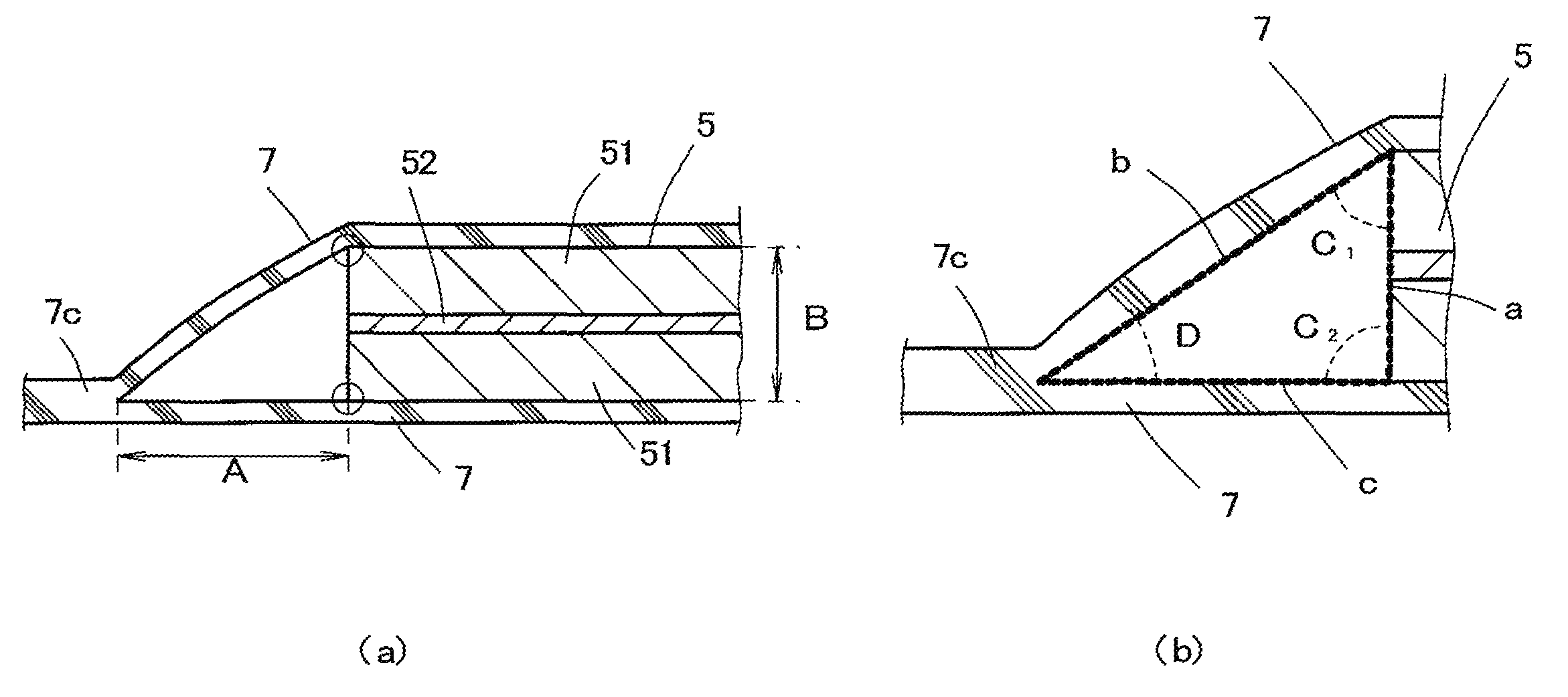
A flat nonaqueous secondary battery with improved reliability is provided. The flat nonaqueous secondary battery (1) includes an electrode assembly disposed in a space formed by an exterior case (2) and a seal case (3). The electrode assembly includes a plurality of positive electrodes (5) and a plurality of negative electrodes (6) alternately stacked upon each other and a separator (7). The separator (7) has a joint (7c) formed by welding together at least a portion of its periphery. When the separator (7) and the positive electrode (5) are measured along a cross section in their thickness direction, the ratio A / B of the shortest distance A between the end of the joint (7c) of the separator (7) facing the positive electrode (5) and the outer periphery of the positive electrode (5) sandwiched by the separator (7) to the thickness B of the positive electrode (5) is not smaller than 1.

Description

TECHNICAL FIELD[0001]The present invention relates to a flat nonaqueous secondary battery with improved reliability.BACKGROUND ART[0002]Flat nonaqueous secondary batteries, often referred to as coin cells or button cells, generally include an electrode complex with positive and negative electrodes stacked upon each other and separated by a separator, and nonaqueous electrolyte, both contained in a space formed by an exterior case and a seal case.[0003]A known flat nonaqueous secondary battery of the above configuration includes positive and negative electrodes that each have a current collector with a positive or negative compound layer on one side or such layers on both sides, where a portion of each current collector has no positive or negative compound layer upon it and thus is exposed to be used as a current collector tab. In such a flat nonaqueous secondary battery, such a current collector tab may be used to establish electrical connection between the collector and an exterior...

Claims


Application Information

Patent Timeline
Patent Type & Authority Patents(United States)
IPC IPC(8): H01M2/18H01M2/02
CPCH01M2/0222H01M10/0585H01M50/109H01M50/411H01M50/463Y02E60/10Y02P70/50H01M50/46H01M50/414H01M50/491H01M50/54
Inventor ONISHI, YUKOYOSHIBA, TOSHIKAZUTAKAI, MEGUMU
Owner MAXELL HLDG LTD
Learn More