Protective Sheath and Method of Using Same for Laser Surgery

Active Publication Date: 2013-08-22
BROWN JOE DENTON
View PDF17 Cites 13 Cited by
  • Summary
  • Abstract
  • Description
  • Claims
  • Application Information

AI Technical Summary

Benefits of technology

[0013]It is accordingly an objective of the invention to provide a protective sheath for a fiber that protects a surgical device, such as an endoscope, through

Problems solved by technology

While such a sheath may provide good protection against mechanical damage to the scope or other instrument through which the fiber is inserted, however, the prior protective sheath designs have a number of disadvantages that have limited their applicability.
The first problem addressed by the present invention is that the previously proposed protective sheaths have the disadvantage that they impede flow of irrigation fluid past the sheath.
While it has been proposed in the above mentioned copending PCT Appl. No. PCT/US2009/006021 to reduce the wall thickness of the sheath, such reduction in the wall thickness of the sheath makes it difficult to detect emission of radiation from the sheath by conventional amplitude detection, especially in applications where the intensity of treatment radiation observed through the scope varies greatly due to changes in the tissue being treated and especially during contact between the fiber and the tissue.
The Applicant has discovered that in may laser surgery procedures, such as urological stone removal, it is

Method used


Image

  • Protective Sheath and Method of Using Same for Laser Surgery
  • Protective Sheath and Method of Using Same for Laser Surgery
  • Protective Sheath and Method of Using Same for Laser Surgery

Examples


Example

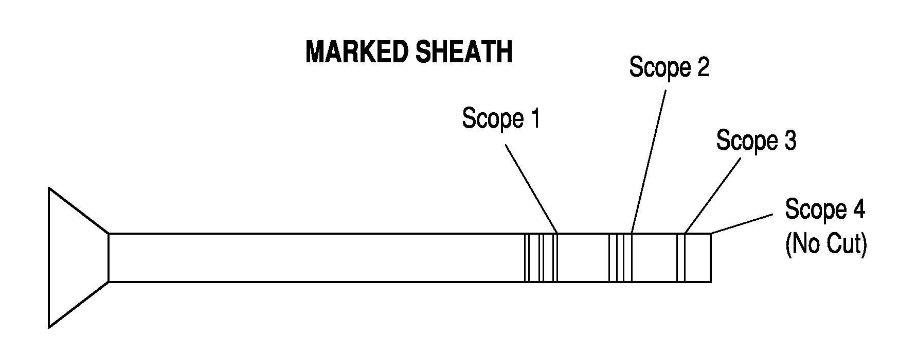
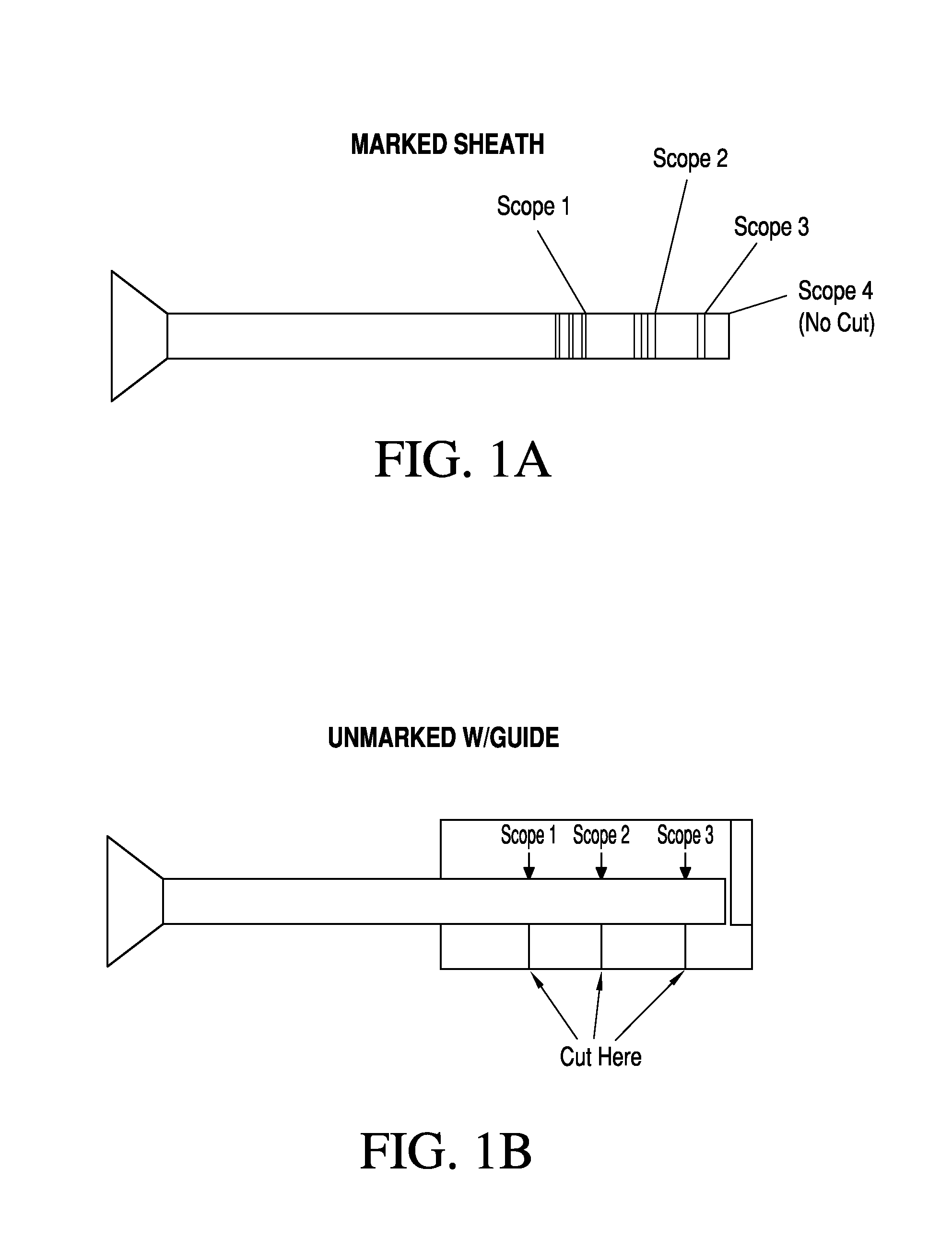
[0030]FIG. 1A shows a fiber sheath with trim markings labeled Scope 1, Scope 2, Scope 3, and Scope 4. The sheath illustrated in FIG. 1A may include the characteristics of extending the length of the fiber and / or of including phosphors according to preferred embodiments of the invention, as described below, although it will be appreciated by those skilled in the art that the trim markings illustrated in FIG. 1A are themselves optional and may be used both with protective sheaths having the characteristics of extending the length of the fiber and / or including phosphors, or with sheaths that do not include those characteristics.

[0031]By extending the lengths of the protective sheath shown in FIG. 1A over the entire length of the fiber, it is possible to prevent mechanical damage caused when the sharp edges of the fiber tip perforates the scopes soft plastic working channel. This is particularly the case when the scope is fully deflected and the fiber tip scores the inside of a plastic ...


PUM

PropertyMeasurementUnit
Thicknessaaaaaaaaaa
Thicknessaaaaaaaaaa
Lengthaaaaaaaaaa

Abstract

A protective sheath is provided to prevent mechanical damage to the working channel of the endoscope during insertion of the fiber, insulate the fiber from surrounding cooling fluids, and/or serve as an indicator of overheating that enables early detection of excess heating or burning of tissues or equipment at the treatment site. The protective sheath may include trim markings to facilitate cutting to a desired length, such as the length of the fiber in the scope, may also be arranged to glow when the fiber is pulled too far into the sheath, may be tightly fitted over the fiber to provide a plunger effect, and may include perforations to facilitate sterilization.

Description

[0001]This application claims the benefit of provisional U.S. Patent Application Ser. Nos. 61 / 721,184, filed Nov. 1, 2012; 61 / 674,058, filed Jul. 20, 2012; and 61 / 596,000, filed Feb. 7, 2012, each of which is incorporated herein by reference.BACKGROUND OF THE INVENTION[0002]1. Field of the Invention[0003]This invention relates to devices and methods for delivering therapeutic light to a tissue, and in particular to optical fiber arrangements in which a protective sheath is placed over the fiber prior to insertion into an endoscope that guides the fiber to a treatment site. The protective sheath prevents mechanical damage to working channel of the endoscope during insertion of the fiber, insulates the fiber from surrounding cooling fluids, protects the fiber when it is extended outside the scope, and may serve as an indicator of overheating that enables early detection of excess heating or burning of tissues or equipment at the treatment site. Preferably, the protective sheath is des...

Claims


Application Information

Patent Timeline
IPC IPC(8): A61B18/22
CPCA61B2018/00107A61B18/22
Inventor BROWN, JOE DENTON
Owner BROWN JOE DENTON
Why Eureka
Try Eureka