Needle assembly for relieving a pneumothorax

a needle and pneumothorax technology, applied in the field of medical technology, can solve the problems of slipping, entanglement of the lung, and the risk of puncturing the lung with straight needles,

Active Publication Date: 2022-05-10
UNIVERSITÄT REGENSBURG UNIVERSITÄTSKLINIKUM
View PDF19 Cites 0 Cited by
  • Summary
  • Abstract
  • Description
  • Claims
  • Application Information

AI Technical Summary

Benefits of technology

[0011]The object of the invention is therefore to provide a simple means for relieving a pneumothorax, which can be used by non-surgically trained personnel and may prepare the patient for direct transport to a surgical operating room, preferably without a further surgical intervention.
[0056]A canula made of surgical steel may provide a limited flexibility for performing an accurate intervention while at the same time providing sufficient rigidity to not be pinched and / or deformed by the respiratory action of the patient, and to define the position of the cutting end in the inserted position of the canula by the shape of the canula. Further, surgical steel may be easily sterilized prior to use.

Problems solved by technology

The known methods and corresponding devices for relieving a pneumothorax entail the problem that medically trained personnel is required at the site of the surgical intervention and that using known needle assemblies does not provide the possibility for a direct and secure transport of the patient after the temporary relief.
In particular, straight needles entail a risk of puncturing the lung and may slide out of the thoracic cavity during transport or the respiratory act of the patient, while semi-flexible tubes can be pinched by the ribs in the thoracic cavity wall and may therefore provide only a temporary relief.

Method used


Image

  • Needle assembly for relieving a pneumothorax
  • Needle assembly for relieving a pneumothorax
  • Needle assembly for relieving a pneumothorax

Examples


Embodiment Construction

[0061]The features and numerous advantages of the needle assembly according to the present invention will best be understood from a detailed description of preferred embodiments with reference to the accompanying drawings, in which:

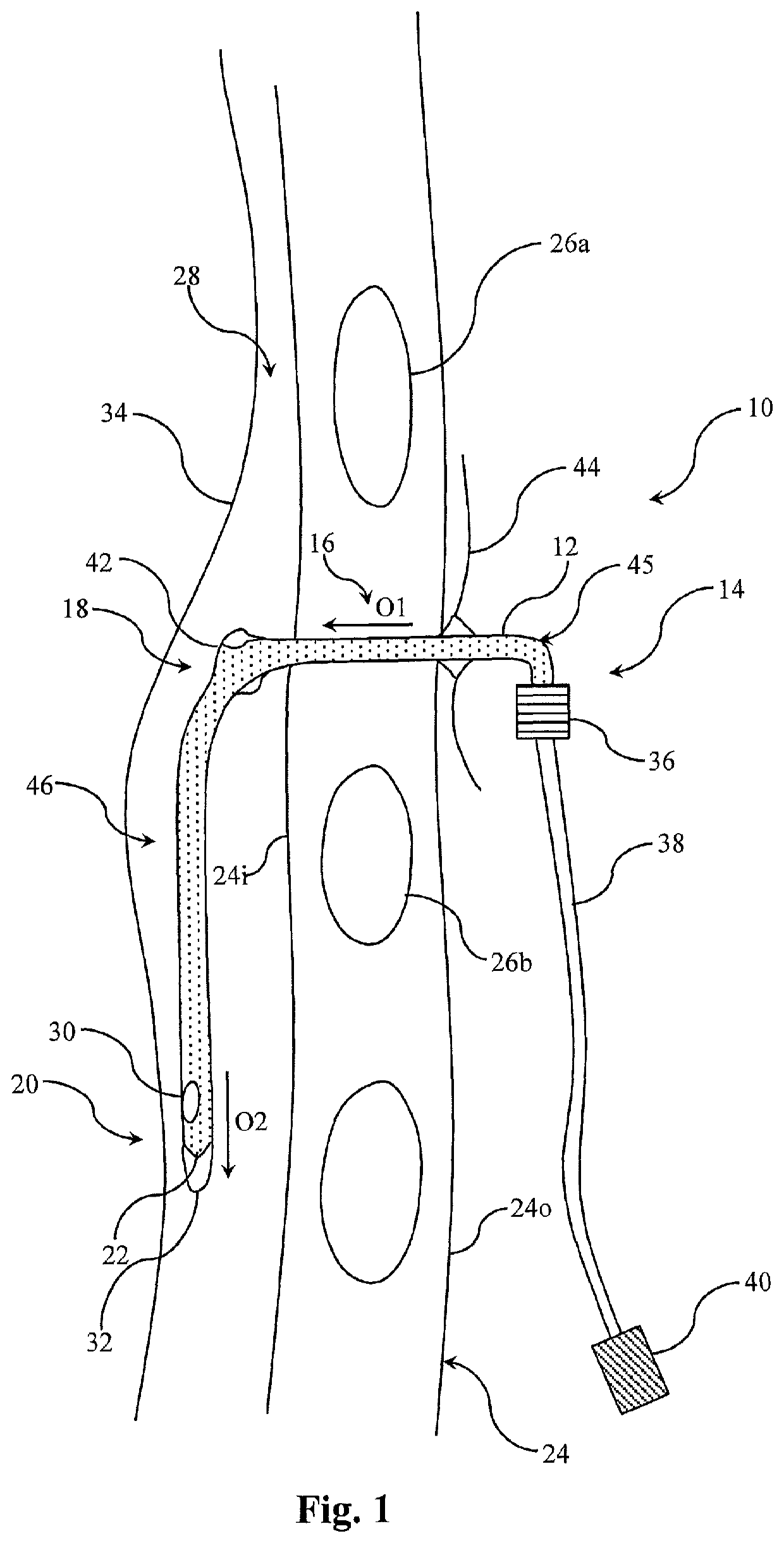
[0062]FIG. 1 is a schematic illustration of a needle assembly in the inserted position according to an example;

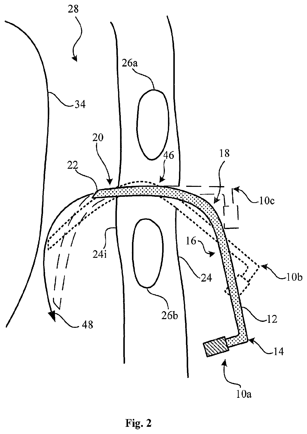
[0063]FIG. 2 is a schematic illustration of an insertion path of an exemplary canula according to an example;

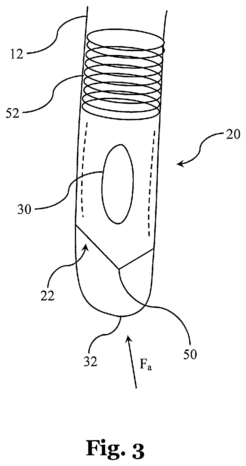
[0064]FIG. 3 is a schematic illustration of a distal end portion of a needle assembly according to an example;

[0065]FIG. 4A is a schematic illustration of a beveled cutting end with a blunt end piece in a protruding position according to an example;

[0066]FIG. 4B is a schematic illustration of a beveled cutting end with a blunt end piece in a retracted position according to an example;

[0067]FIG. 4C is a schematic illustration of the distal end portion viewed along an axial direction of the canula illustrating the position of the tip accordi...


PUM


Abstract

A needle assembly (10) for relieving a pneumothorax and / or a hemothorax, the needle assembly (10) comprising a canula (12), the canula (12) comprising: a distal end portion (20) comprising a cutting end (22) for puncturing a thoracic cavity wall (24), a proximal end portion (14) for removing a fluid or gas from a thoracic cavity (28), a first curved portion (18) between the distal end portion (20) and the proximal end portion (14), an intermediate portion (16) between the first curved portion (18) and the proximal end portion (14), and a first fixing bulge (42) arranged between the first curved portion (18) and the intermediate portion (16), wherein an outer diameter of the canula (12) at the first fixing bulge (42) is increased with respect to the diameter (D1) of the intermediate portion (16), said first fixing bulge (42) being arranged such as to be placed at or close to the inner surface (24) of the thoracic cavity wall (24i), when the canula (12) is inserted for relieving the pneumothorax, such as to prevent or to reduce the risk that the canula (12) inadvertently slides out of its inserted position.

Description

CROSS-REFERENCE TO RELATED APPLICATIONS[0001]This application is the national phase entry of International Patent Application No. PCT / EP2018 / 080968 filed on Nov. 12, 2018, and claims the benefit of EP Patent Application No. 17202544.7 filed Nov. 20, 2017, the disclosures of which are incorporated herein by reference in their entirety.FIELD OF THE INVENTION[0002]The present invention is in the field of medical technology. More precisely, the present invention relates to a needle assembly for relieving a pneumothorax.BACKGROUND[0003]The lung of a human retains its shape through a vacuum in the pleural cavity between the visceral and the parietal pleura, i.e. between the lung and the thoracic cavity wall. Thus, the movement of the thoracic cavity wall or the thoracic diaphragm can inflate or deflate the lung during the respiratory act. A pneumothorax is a medical condition, wherein air or a liquid, such as blood (hemothorax), chyle (chylothorax) or transudate (hydrothorax), collects in...

Claims


Application Information

Patent Timeline
Patent Type & Authority Patents(United States)
IPC IPC(8): A61B17/34A61B17/00
CPCA61B17/3421A61B17/3415A61B17/3474A61B2017/00809A61B2017/00862A61B2017/3456A61B17/3496A61B2017/3488A61B2017/3492
Inventor SCHICHO, ANDREAS JOHANNES
Owner UNIVERSITÄT REGENSBURG UNIVERSITÄTSKLINIKUM
Why Eureka
Try Eureka