Sanding device

Pending Publication Date: 2021-10-28
HATFIELD JOHN WINFRED
View PDF0 Cites 0 Cited by
  • Summary
  • Abstract
  • Description
  • Claims
  • Application Information

AI Technical Summary

Benefits of technology

[0022]As will be apparent to one skilled in the art from the accompanying description and drawings, sanding devices according to preferred embodiments of the invention incorporate a handle to provide rigidity along the width of the blade ensuring that the blade does not flex along the axis of its width but can flex along the axis of its depth, in that the flexibility of the blade is limited to providing sprung pressure along the depth of the blade only. The sanding device utilises the sprung energy of bending the blade to provide pres

Problems solved by technology

Difficulties arise when sanding right up to an edge of an adjacent vertical surface or into a corner with adjacent vertical surfaces on two sides.
When faced with these difficult areas, powered sanders, where the sanding abrasive surface oscillates at high speed, bounce out of the corners and off the raised adjacent surfaces, providing a poor abraded finish and often damage the adjacent surfaces.
A sanding block will only sand into a corner if there is areas that the sanding block can access usefully because the attachment hardware obstructs effective sandin

Method used


Image

  • Sanding device
  • Sanding device
  • Sanding device

Examples


Embodiment Construction

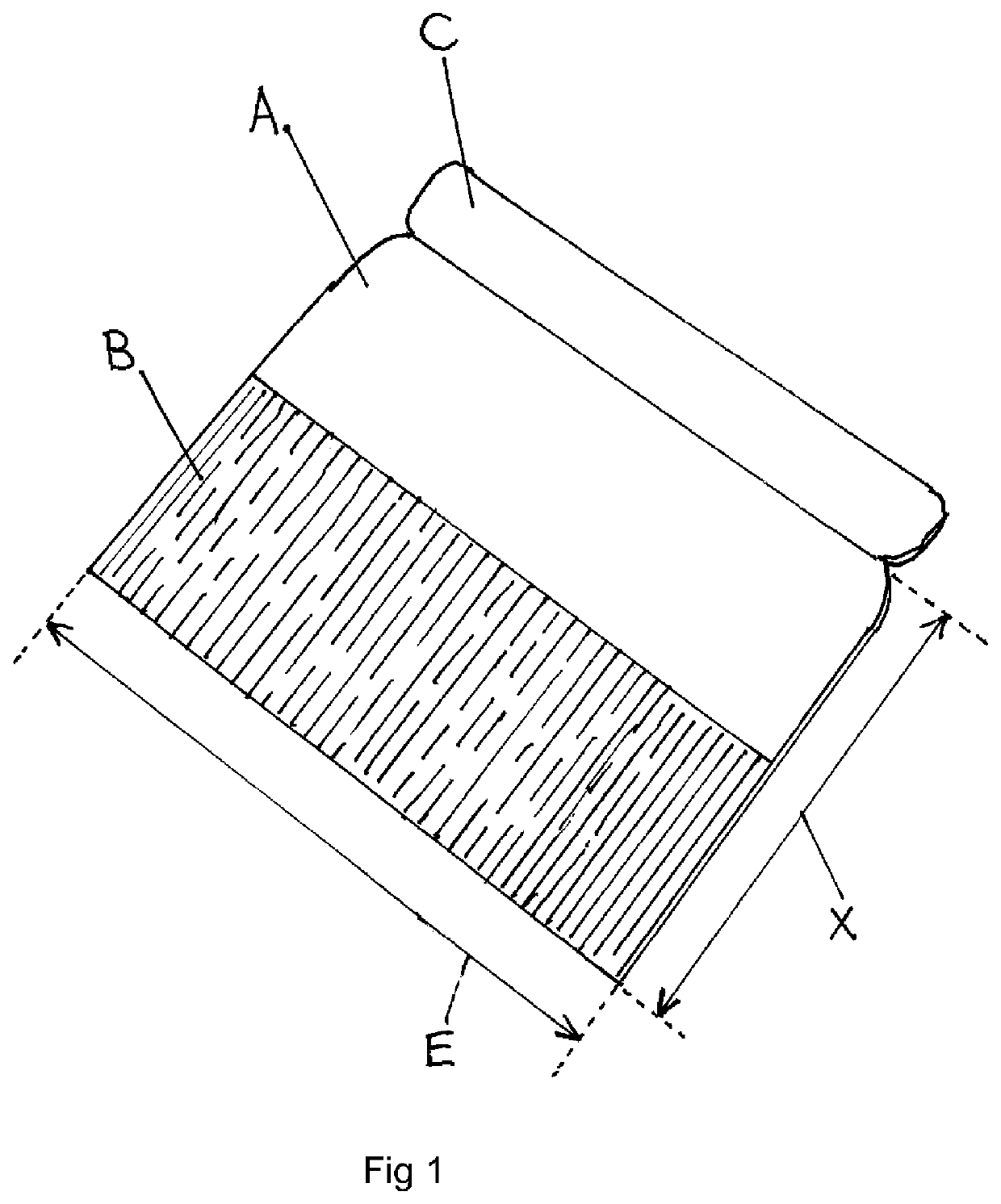
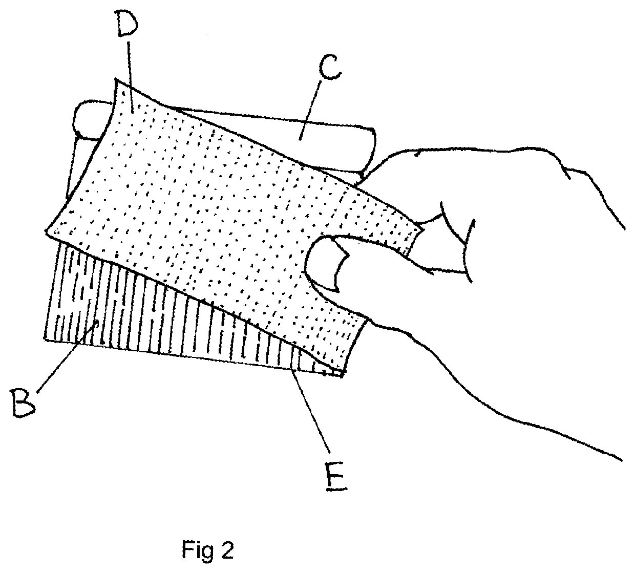
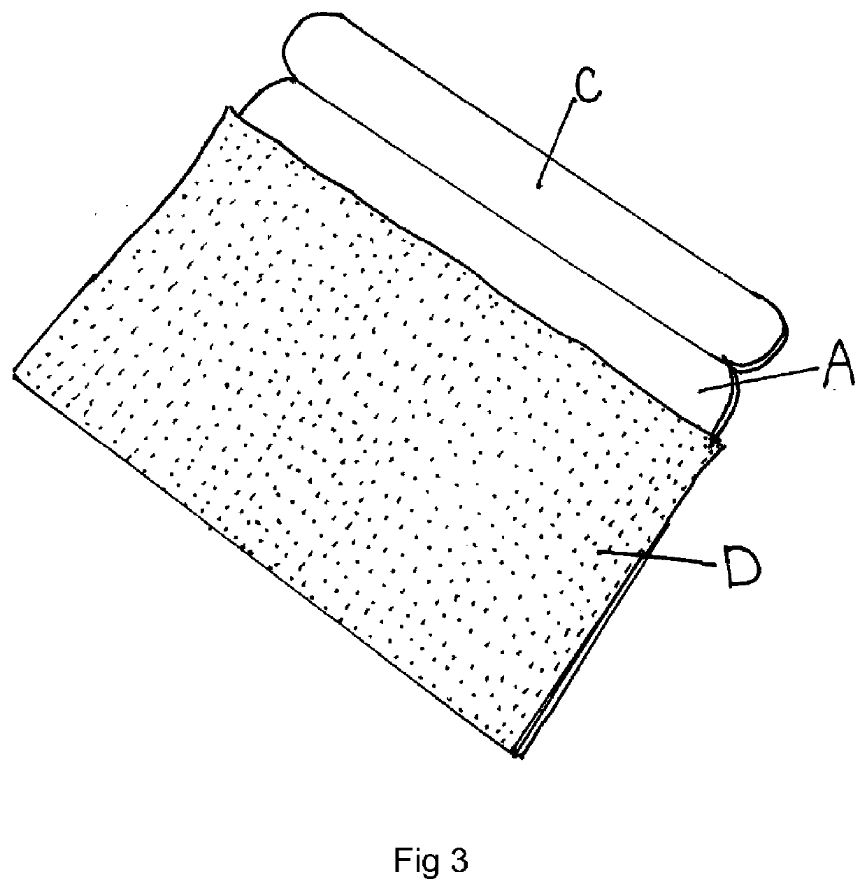
[0030]Referring to the drawings, FIG. 1 shows the sanding device according to the invention without any abrasive paper attached. The device comprises a generally rectilinear blade (A), formed of moulded polypropylene and having a 115 mm long edge (E), a 100 mm short edge (X) forming an angle 90° with the long edge (E) and a thickness of 1.5 mm, a hook fastener strip (B) that is the hook component of a hook & loop fastener and is permanently fixed to one side of the blade (A). The other side of the blade (A) is bare and has no hook fastener strip. Starting from the abrasive straight long edge (E), the hook fastener strip (B) extends across the full width of the blade (A) and to just over half the depth of the blade (A). This is preferable, although the hook element (B) could extend of the blade so that there is no flexibility in the blade across its width. The blade (A) is intended to only flex along the depth axis which runs between the abrasive edge (E) and the handle (C). The han...


PUM


Abstract

attached to the surface. A handle (C) is attached to one edge of the blade (A) in order to stiffen the blade (A) so that the blade is stiff around one axis lying in a plane normal to the plane of the blade and normal to the handle and is flexible around an axis normal to the plane of the blade and parallel to the handle. The sanding device facilitates abrasion of surfaces in corners and rebates without undesirably abrading the adjacent surface.

Description

[0001][0002]This invention relates to a device for abrading detailed surfaces and surfaces of abradable material, especially, but not limited to, surfaces formed of wood in difficult to reach areas, examples are edges, corners, grooves, and small areas of a flat surface.BACKGROUND[0003]Sanding a large flat surface is straightforward and many known devices achieve a satisfactory result. Difficulties arise when sanding right up to an edge of an adjacent vertical surface or into a corner with adjacent vertical surfaces on two sides. A good example is sanding a cupboard door where the typically recessed central panel meets with the raised framed sides known as rails and stiles. When faced with these difficult areas, powered sanders, where the sanding abrasive surface oscillates at high speed, bounce out of the corners and off the raised adjacent surfaces, providing a poor abraded finish and often damage the adjacent surfaces. For this reason, much detail sanding is undertaken by hand. T...

Claims


Application Information

Patent Timeline
IPC IPC(8): B24D15/04
CPCB24D15/04
Inventor HATFIELD, JOHN WINFRED
Owner HATFIELD JOHN WINFRED
Why Eureka
Try Eureka