Joint imaging apparatus

Inactive Publication Date: 2013-09-05
KONICA MINOLTA INC
View PDF4 Cites 23 Cited by
  • Summary
  • Abstract
  • Description
  • Claims
  • Application Information

AI Technical Summary

Benefits of technology

[0017]In view of such circumstances, an object of the present invention is to provide an imaging apparatus that includes a subject table that can firml

Problems solved by technology

Images taken by magnetic resonance imaging (MRI) have mainly been used for diagnosis of rheumatoid arthritis because conventional radiographic techniques using an absorption contrast method cannot create images suitable for diagnosis of cartilages in joints of limbs and soft tissues around joints.
Unfortunately, MRI forces a heavy burden on a patient because of holding a posture of the patient under restraint mechanically for a predetermined time period and costs a great deal of money; hence, technology is needed that diagnoses rheumatism using X-ray images taken with common X-ray tubes.
The radiography using such a phase contrast method can image breast tissues, joint cartilages, and soft tissues around joints, which cannot readily produce clear im

Method used


Image

  • Joint imaging apparatus
  • Joint imaging apparatus
  • Joint imaging apparatus

Examples


Example

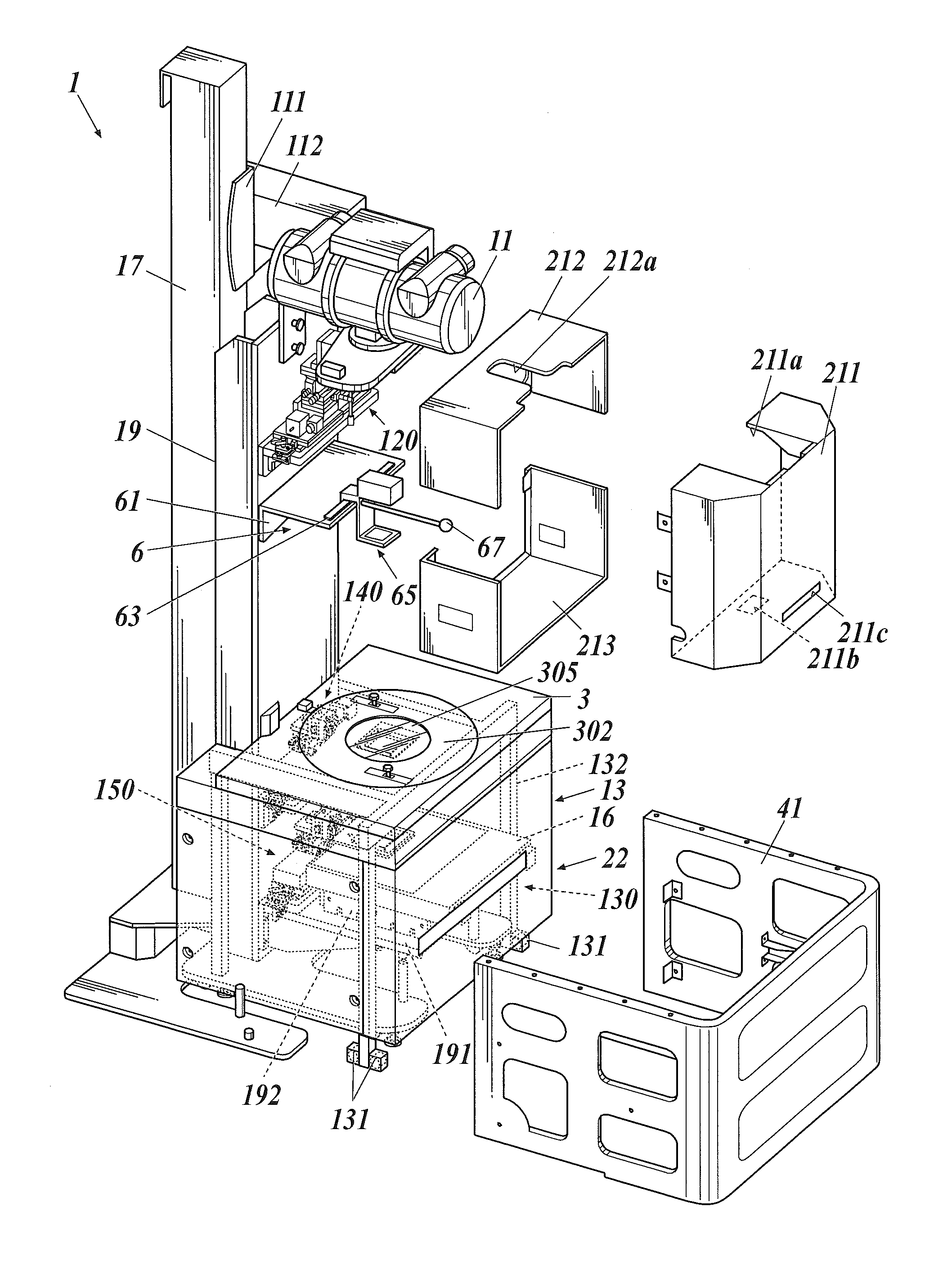
[0085]An embodiment of a joint imaging apparatus according to the present invention will now be described with reference to the accompanying drawings.

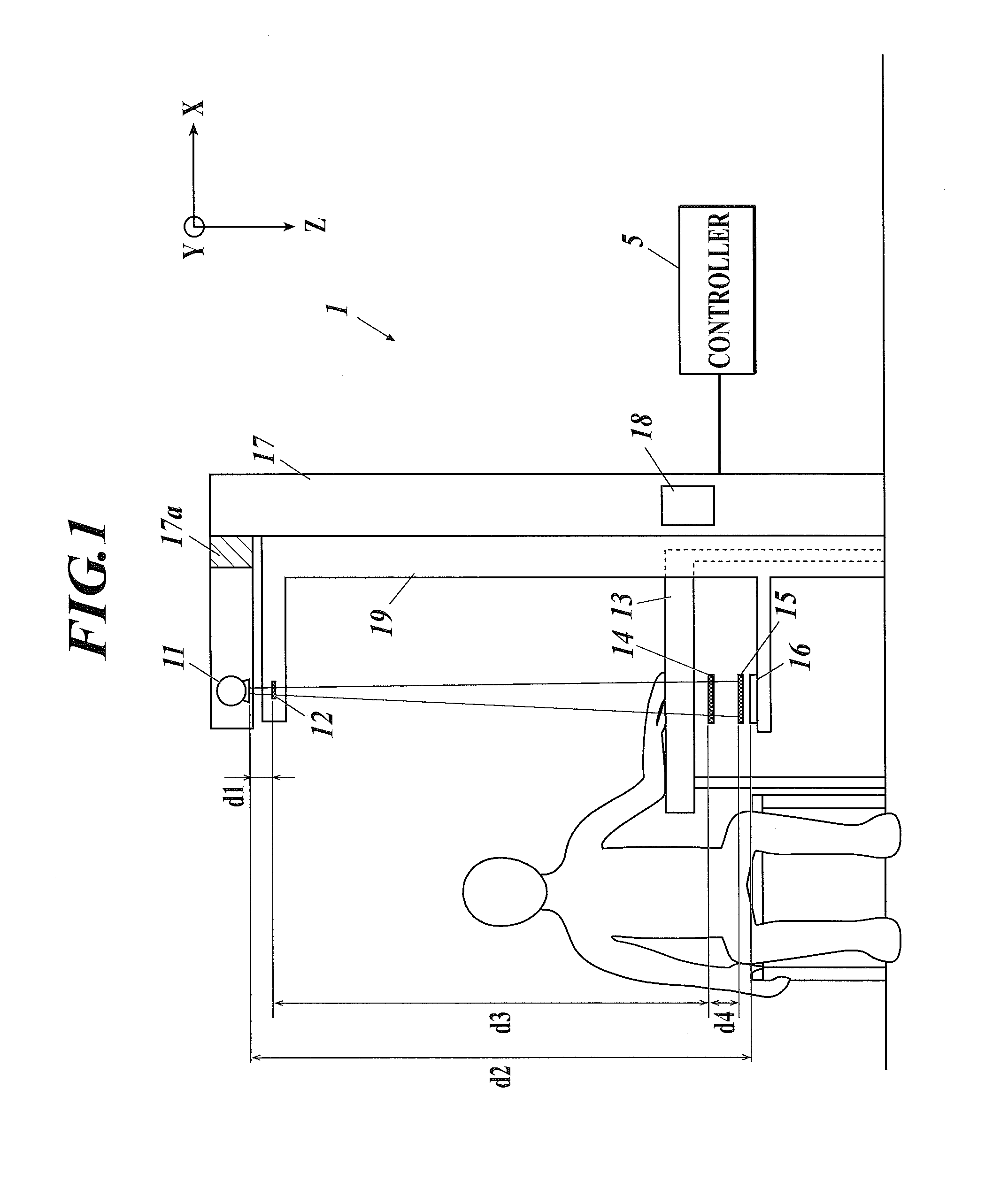
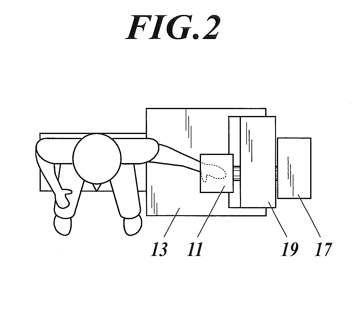
[0086]The joint imaging apparatus 1 in the present embodiment includes a radiographic unit and a subject table 13. The subject table 13 holds a subject such as a human finger on a position for radiography. The radiographic unit includes an X-ray source 11 (radiation generating section) and an X-ray detector 16 (detecting section). The X-ray source 11 is disposed above the subject table 13 to irradiate a subject, such as a joint of a finger with X-rays. The X-ray detector 16 is disposed under the subject table 13 to detect X-rays that pass through the joint.

[0087]FIG. 1 schematically illustrates an X-ray imaging system including the joint imaging apparatus 1 according to the present embodiment, and FIG. 2 is a top plan view illustrating the joint imaging apparatus 1 in FIG. 1.

[0088]The X-ray imaging system includes the joint imaging app...


PUM


Abstract

A joint imaging apparatus includes a subject table and a radiographic unit including a radiation generating section disposed above the subject table to irradiate a joint of a finger, and a detecting section disposed under the subject table to detect radiation passing through the joint. The subject table includes a base unit to fix the wrist, and a subject fixing unit to fix the joint to a predetermined position. The subject fixing unit includes a first fixing member to fix a part on the trunk side of the joint, and a second fixing member to fix a part on the side, opposite to the trunk side, of the joint. A position of the second fixing member is adjustable relative to that of the first fixing member.

Description

CROSS REFERENCE TO RELATED APPLICATIONS[0001]The present invention claims priority under 35 U.S.C. §119 to Japanese Application No. 2012-045313 filed Mar. 1, 2012, the entire content of which is incorporated herein by reference.BACKGROUND OF THE INVENTION[0002]1. Field of the Invention[0003]The present invention relates to a joint imaging apparatus.[0004]2. Description of Related Art[0005]Images taken by magnetic resonance imaging (MRI) have mainly been used for diagnosis of rheumatoid arthritis because conventional radiographic techniques using an absorption contrast method cannot create images suitable for diagnosis of cartilages in joints of limbs and soft tissues around joints.[0006]Unfortunately, MRI forces a heavy burden on a patient because of holding a posture of the patient under restraint mechanically for a predetermined time period and costs a great deal of money; hence, technology is needed that diagnoses rheumatism using X-ray images taken with common X-ray tubes.[0007]...

Claims


Application Information

Patent Timeline
IPC IPC(8): A61B6/04
CPCA61B6/04A61B6/582A61B6/585A61B6/484
Inventor HOSHINO, YOSHIHIDENISHINO, SATOSHI
Owner KONICA MINOLTA INC
Why Eureka
Try Eureka