Eyeglass frame with input and output functionality

Active Publication Date: 2013-09-12
GOOGLE LLC
View PDF4 Cites 276 Cited by
  • Summary
  • Abstract
  • Description
  • Claims
  • Application Information

AI Technical Summary

Benefits of technology

[0009]Another aspect of the present disclosure relates to an electronic device, including a frame configured to be worn on the head of a user. The frame includes first and second rims with lenses affixed therein and a bridge portion positioned between the first and second rims and configured to rest on a portion of the nose of the user. The frame further includes first and second temple portions extending away from the rims to respective ends thereof that are configured to be positioned over respective first and second temples of the user with the ends disposed near first and second ears of the user. The device further includes a display element positionable over one of the first and second lenses and a housing having an arm portion affixed to the first temple portion of the frame and defining a longitudinal axis, the housing also including an elbow portion defining a display

Problems solved by technology

Regardless of the type of image presented to the user, such devices are usually blacked-out.
That is, they almost entirely obstruct the wearer's vision outside of the screen or other image source included therein so that the user can see nothing but the image presented by the device's display system.
Such devices, howev

Method used


Image

  • Eyeglass frame with input and output functionality
  • Eyeglass frame with input and output functionality
  • Eyeglass frame with input and output functionality

Examples


Embodiment Construction

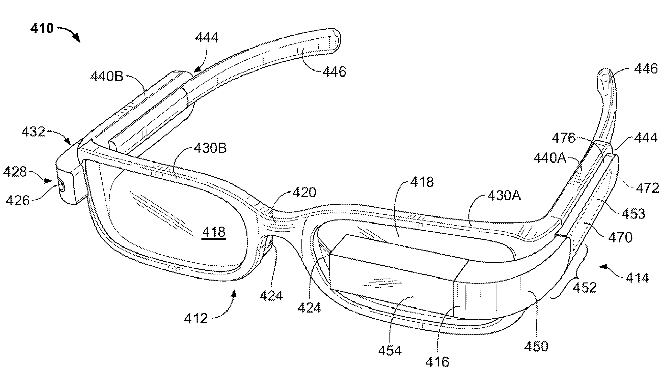
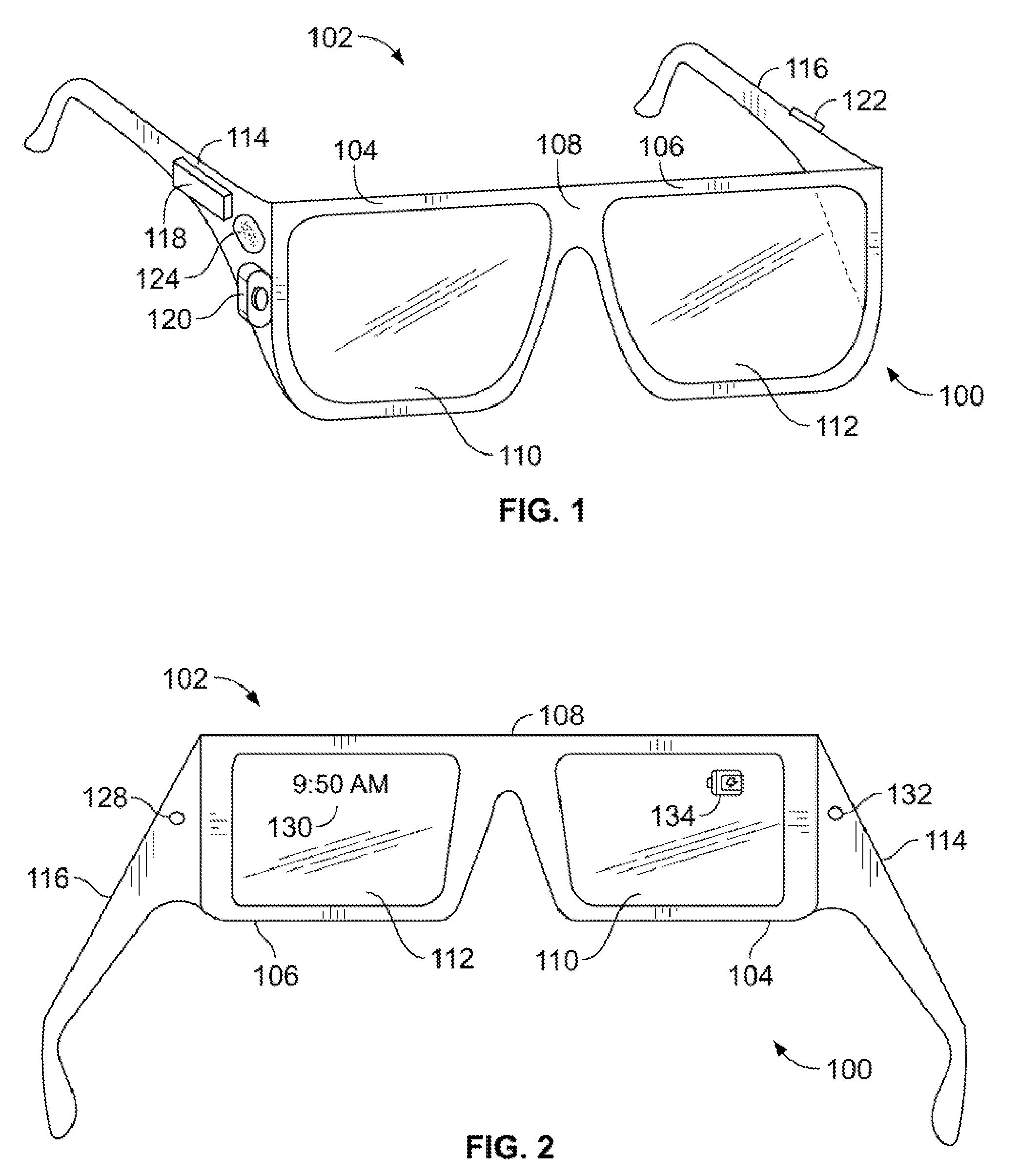
[0028]Embodiments of the present disclosure are described herein with reference to the drawing figures. FIG. 1 illustrates an example system 100 for receiving, transmitting, and displaying data. The system 100 is shown in the form of a wearable computing device. While FIG. 1 illustrates a head-mounted device 102 as an example of a wearable computing device, other types of wearable computing devices could additionally or alternatively be used. As illustrated in FIG. 1, the head-mounted device 102 comprises frame elements including lens-frames 104, 106 and a center frame support 108, lens elements 110, 112, and extending side-arms 114, 116. The center frame support 108 and the extending side-arms 114, 116 are configured to secure the head-mounted device 102 to a user's face via a user's nose and ears, respectively.

[0029]Each of the frame elements 104, 106, and 108 and the extending side-arms 114, 116 may be formed of a solid structure of plastic and / or metal, or may be formed of a hol...


PUM


Abstract

An electronic device includes a frame configured to be worn on the head of a user and having first and second rims with lenses and a bridge between the rims for resting on the nose of the user. First and second temple portions extend away from the rims to ends and are can be positioned over the temples of the user with the ends near the ears of the user. The device further includes a display element over one of the lenses and a housing having an arm portion affixed to the first temple portion. An elbow portion of the housing defines a display end that supports the display element at an angle to the arm portion. Image generating means within the housing can present an image on the display element. An input device on the housing can receive an input from the user.

Description

BACKGROUND[0001]Personal video or image displays are devices that are used to display an image received from a source for viewing by a single user. Such devices can be in the form of head-mounted displays that are worn on the head of a user and include one or more image sources over or in front of the user's eyes. Head-mounted displays can include an image source positioned adjacent and associated with each eye of the user or wearer and can be configured to present the same image, viewable as a single two-dimensional image. Alternatively, some such devices can be configured to present different stereoscopic images that are interpreted by the viewer as a single three-dimensional image. Regardless of the type of image presented to the user, such devices are usually blacked-out. That is, they almost entirely obstruct the wearer's vision outside of the screen or other image source included therein so that the user can see nothing but the image presented by the device's display system.[0...

Claims


Application Information

Patent Timeline
IPC IPC(8): G02C11/00
CPCG02C11/10G02B2027/0138G02B27/017G02B2027/0178
Inventor HEINRICH, MITCHELL JOSEPHOLSSON, MAJ ISABELLE
Owner GOOGLE LLC
Why Eureka
Try Eureka