Multi-ferrule connector for multicore fiber terminations

a multi-ferrule connector and fiber termination technology, applied in the field of fiber optics, can solve the problems of difficult and costly use of current mt-type connectors for mcfs, difficult and costly to terminate a set of mcfs with prior multifiber connectors, and difficult to manipulate individual fibers for multicore alignment, etc., to achieve high density packing footprint

Active Publication Date: 2013-10-03
OFS FITEL LLC
View PDF18 Cites 73 Cited by
  • Summary
  • Abstract
  • Description
  • Claims
  • Application Information

AI Technical Summary

Benefits of technology

[0015]An aspect of the invention provides a multifiber connector for terminating a set of multicore fibers. A ganged connector housing is configured to receive a plurality of single-fiber connectors. Each connector is removably retainable at a respective location in the connector housing. Each single-fiber connector comprises a ferrule configured to receive and retain a single multicore fiber. The single-fiber connectors have a high-density packing footprint within the connector housing. Each single-fiber connector and its respective ferrule is configured to enable individual repositioning, tuning, alignment, repair or replacement of a respective multicore fiber terminated therein, independent of other optical fibers within the plurality of single fiber ferrules, and without requiring replacement of the entire set of multicore fibers.

Problems solved by technology

However, the use of prior multifiber connectors to terminate a set of MCFs is problematic.
Because of the lack of easy tuning and positioning of the cores of individual MCFs as well as the lack of a way to easily replace individual dark channels, it is difficult and costly to use current MT-type connectors for MCFs.
Further, manipulating individual fibers for multicore alignment Is difficult, if not impossible, given that the typical center-to-center spacing between adjacent fibers is on the order of 250 μm.
In addition, some MCFs are provided with a helically twisted core configuration, thus making pre-alignment solutions are difficult to implement,

Method used


Image

  • Multi-ferrule connector for multicore fiber terminations
  • Multi-ferrule connector for multicore fiber terminations
  • Multi-ferrule connector for multicore fiber terminations

Examples


Embodiment Construction

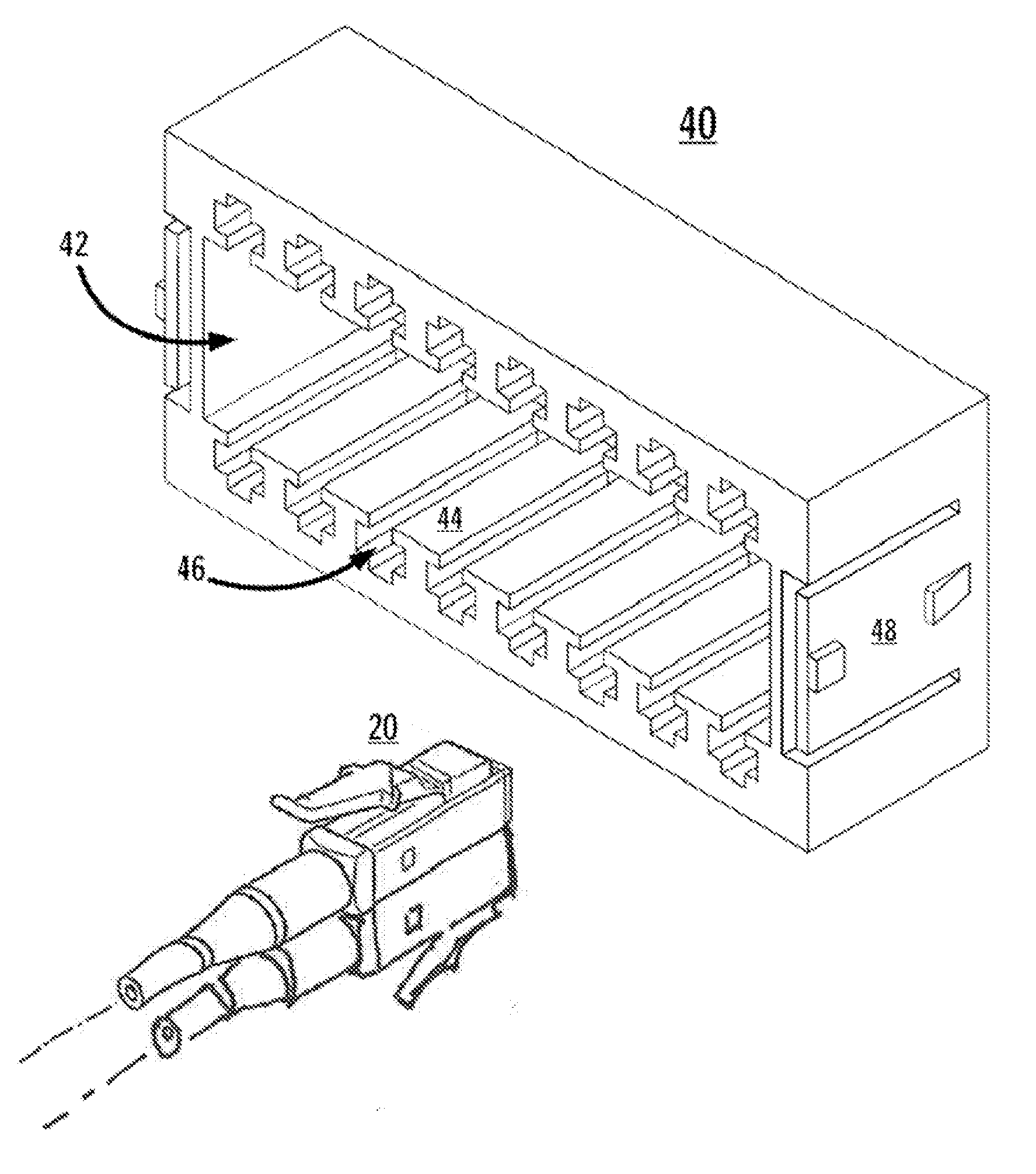
[0025]The present invention is directed to a multifiber connector design for multicore fibers (MCFs), in which a plurality of individual single-fiber connectors or connector elements are packed into a “ganged” connector housing, so as to have a high-density packing footprint. As used herein, the term “high-density packing footprint” refers to a packing configuration in which the distance between neighboring connectors is minimized, so as to achieve a highly efficient use of space. The structures and techniques described herein provide easy-to-use and economical solutions to the tuning, positioning, and channel replacement issues described above.

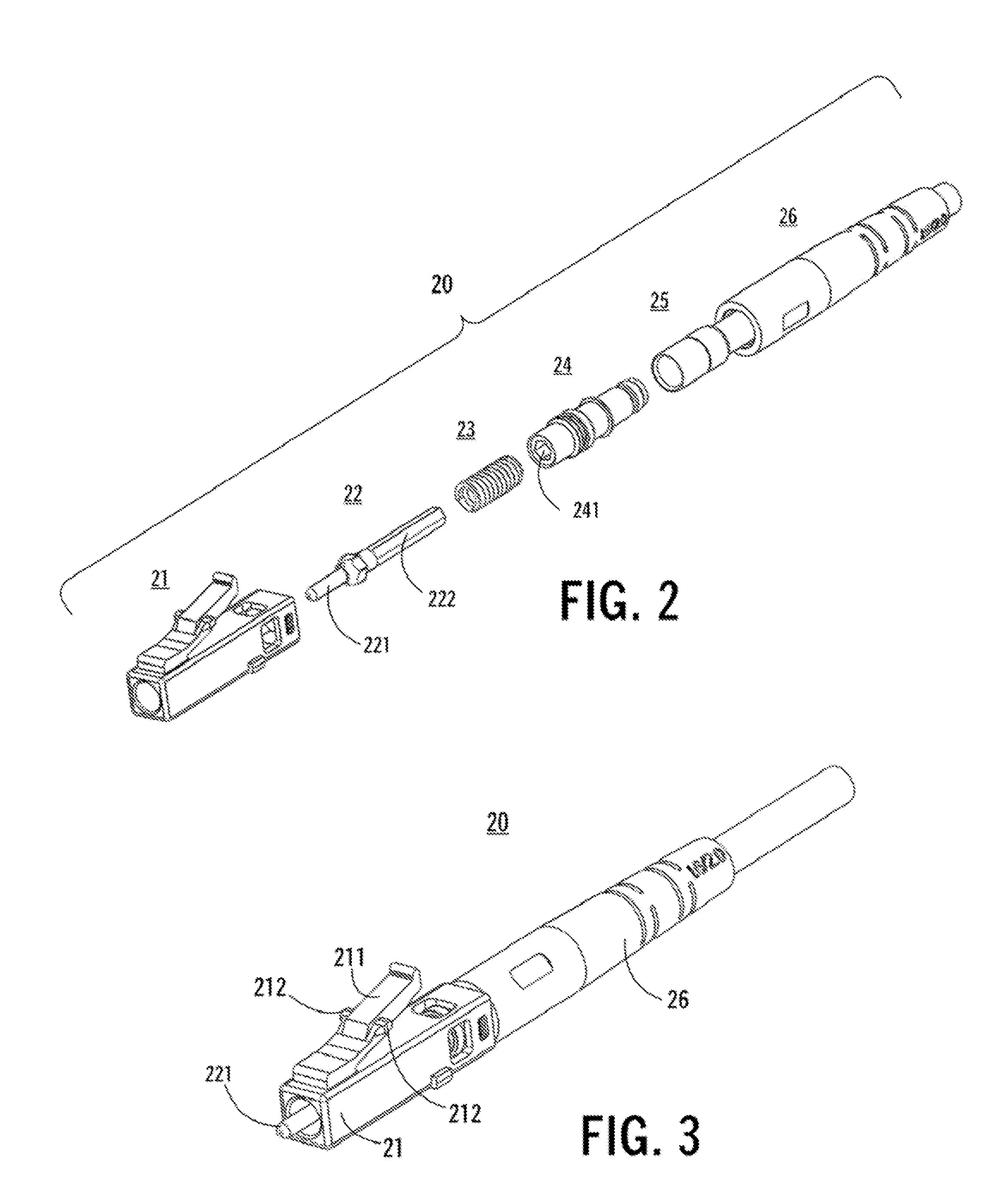
[0026]In an exemplary practice of the invention, each individual MCF in a set of MCFs is terminated with a respective single-fiber connector. The single-fiber connectors are then stacked and loaded into a “ganged” housing that functions as a single multifiber connector unit, in which the MCF endfaces all lie in the same plane and have a preci...


PUM


Abstract

A ganged connector housing Is configured to receive a plurality of single-fiber connectors. Each connector is removably retainable at a respective location in the connector housing. Each single-fiber connector comprises a ferrule configured to receive and retain a single multicore fiber. The single-fiber connectors have a high-density packing footprint within the connector housing. Each single-fiber connector and its respective ferrule is configured to enable individual repositioning, tuning, alignment, repair or replacement of a respective multicore fiber terminated therein, independent of other optical fibers within the plurality of single fiber ferrules, and without requiring replacement of the entire set of multicore fibers.

Description

CROSS REFERENCE TO RELATED APPLICATIONS[0001]The present application claims the priority benefit of U.S. Provisional Patent Application Ser. No. 61 / 651,126, filed on May 24, 2012, which is owned by the assignee of the present invention, and which is incorporated herein by reference in its entirety.[0002]The present application is a continuation-in-part of the following co-pending patent applications:[0003]“Simplex Connectors For Multicore Optical Fiber Cables” U.S. patent Application Ser. No. 13 / 049,780, filed on Mar. 16, 2011, published on Sep. 22, 2011, as United States Application Publication No. 2011 / 0229085; and.[0004]“Multifiber Connectors For Multicore Optical Fiber Cables,” U.S. patent application Ser. No. 13 / 049,794, filed on Mar. 16, 2011, published on Sep. 22, 2011, as United States Application Publication No. 2011 / 0229086,both of which claim the priority benefit of U.S. Provisional Patent Application Ser. No. 61 / 314,165, filed on Mar. 16, 2010.[0005]The above application...

Claims


Application Information

Patent Timeline
Patent Type & Authority Applications(United States)
IPC IPC(8): G02B6/38
CPCG02B6/3851G02B6/381G02B6/3893G02B6/3885G02B6/3879G02B6/3871
Inventor CZOSNOWSKI, WLADYSLAWSANDELS, GREGORY A.
Owner OFS FITEL LLC
Why Eureka
Try Eureka