Node device

Active Publication Date: 2013-10-31
NEC CORP
View PDF6 Cites 1 Cited by
  • Summary
  • Abstract
  • Description
  • Claims
  • Application Information

AI Technical Summary

Benefits of technology

The technical effect of the patent text is to prevent a wasteful allocation of channels to a radio interface. This is achieved through a configuration that ensures efficient use of available resources.

Problems solved by technology

Moreover, even when a channel is allocated to a radio interface, there is a case that a communication link using the channel is not established.
In a case that a channel is thus allocated to a radio interface wastefully, the following problems arise.
In this case, when some of the node devices are not using the channel for communication links set as use communication links, the timeslots allocated to the channel are wasted (are not used for transfer of data).
Further, in a case that there is a channel which is not used for a communication link set as a use communication link, electric power is wasted because electric power is supplied to a radio interface to which the channel is allocated.
Thus, because a node device used in the abovementioned technique is kept in a state that a channel is wastefully allocated to a radio interface, the problems as described above arise.
Such problems also arise in a communication network other than a cognitive radio network.
For example, such problems also arise in a multi-hop communication network that performs multi-hop communication.

Method used


Image

  • Node device
  • Node device
  • Node device

Examples


first exemplary embodiment

(Configuration)

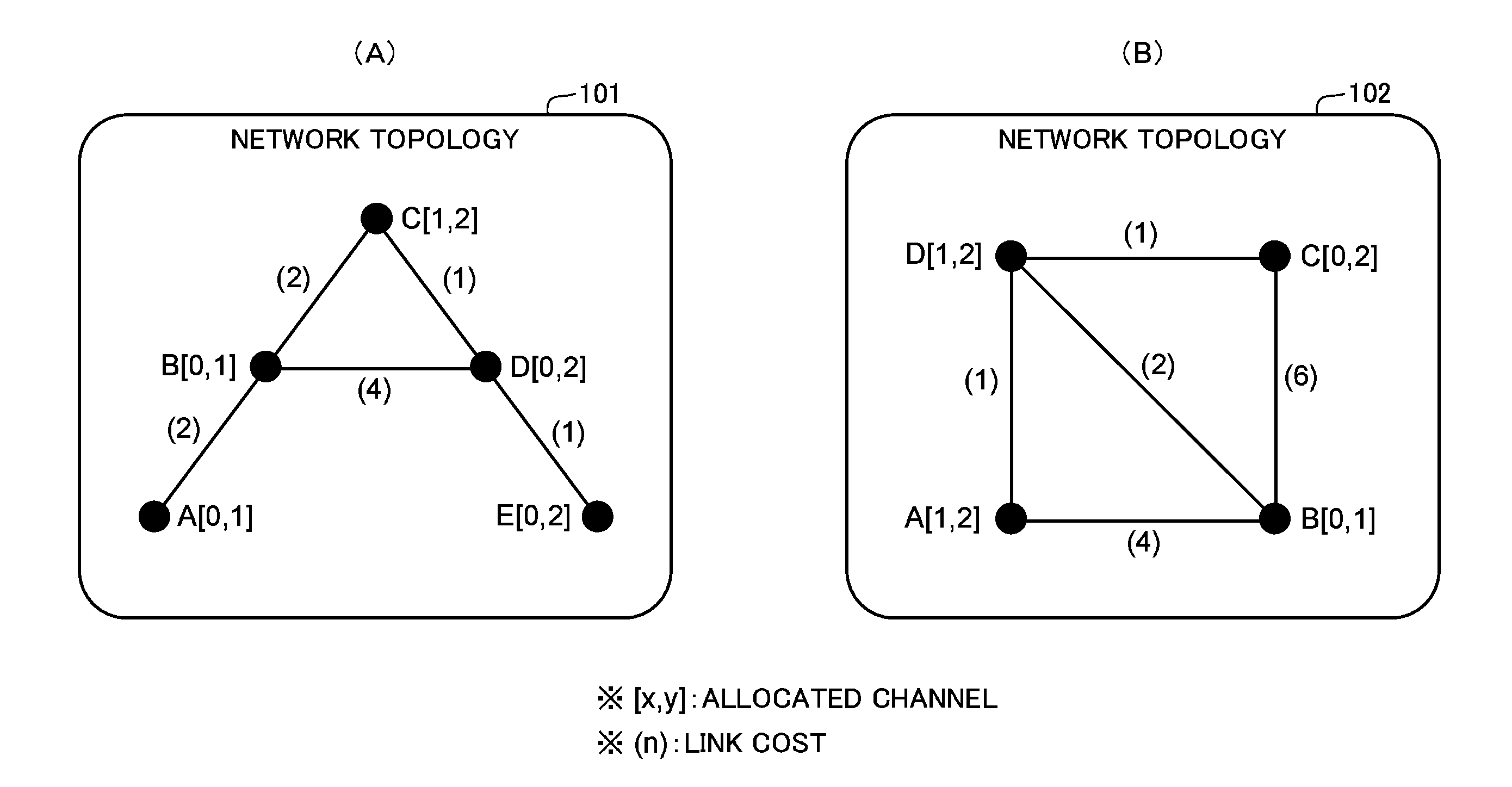
[0078]Next, a first exemplary embodiment of the present invention will be described in detail with reference to the drawings.

[0079]With reference to FIG. 2, a communication system according to the first exemplary embodiment of the present invention includes a node device (also referred to as a “node” hereinafter) A1 and a node device A2. The communication system according to the first exemplary embodiment also includes another node device that is not shown in the drawings.

[0080]In this exemplary embodiment, the communication system is a multi-hop communication system that performs multi-hop communication. Multi-hop communication is communication in which a node configured by a terminal device transfers data received from another node (i.e., relays transmission of the data) and the data is thereby transmitted between the nodes. That is to say, the respective nodes configure the multi-hop communication network.

[0081]Further, in this exemplary embodiment, each of the nod...

second exemplary embodiment

[0179]Next, a communication system according to a second exemplary embodiment of the present invention will be described. The communication system according to the second exemplary embodiment is different from the communication system according to the first exemplary embodiment in specifying a channel other than a channel used in a communication link set as an auxiliary communication link, as an unused channel. Therefore, a description will be made below focusing on the different point.

[0180]With reference to FIG. 9, the communication system according to the second exemplary embodiment of the present invention includes a node A3 and a node A4 instead of the node A1 and the node A2 of the first exemplary embodiment. The communication system according to the second exemplary embodiment also includes another node that is not shown in the drawings.

[0181]Each of the nodes has the same configuration and function as the node A3. Therefore, only the node A3 will be described below. A config...

third exemplary embodiment

[0238]Next, a communication system according to a third exemplary embodiment of the present invention will be described. The communication system according to the third exemplary embodiment is different from the communication system according to the first exemplary embodiment in specifying a channel other than a minimum cost channel for each of the adjacent nodes, as an unused channel. Therefore, a description will be made below focusing on the different point.

[0239]With reference to FIG. 14, the communication system according to the third exemplary embodiment of the present invention includes a node A5 and a node A6 instead of the node A1 and the node A2 in the first exemplary embodiment. The communication system according to the third exemplary embodiment also includes another node that is not shown in the drawings.

[0240]Each of the nodes has the same configuration and function as the node A5. Therefore, only the node A5 will be described below. In FIG. 14, a configuration and fun...


PUM


Abstract

A node device 100 is configured to: allocate a channel for communication to each of radio interfaces; between the radio interface and a radio interface which is included by an adjacent node device and to which the same channel as the channel allocated to the radio interface is allocated, establish a communication link using the channels; and, by using a communication link (a use communication link) set for the destination of received data among established communication links, transfer the data to the adjacent node device. The node device 100 specifies an unused channel that is other than a channel used by a communication link set as the use communication link among already allocated channels (101), and releases allocation of the unused channel (102).

Description

TECHNICAL FIELD[0001]The present invention relates to a node device having a radio interface and configuring a multi-hop communication network.BACKGROUND ART[0002]An expectation of realization of a cognitive radio network has been increasing. A cognitive radio network enables configuration of a communication network fit for an ambient environment, because each of node devices configuring the communication network performs communication by selecting one or more channels from among a plurality of candidates of a utilizable radio communication frequency (hereinafter, referred to as a channel) based on the ambient environment (an unused channel, a distance between node devices, a required communication bandwidth (a communication demand), and so on).[0003]In a cognitive radio network, when any two node devices that the same channel is allocated exist within a distance that mutual propagation (communication) is allowed, a communication link using the channel is established between the nod...

Claims


Application Information

Patent Timeline
IPC IPC(8): H04W72/04
CPCH04W40/24H04W72/04H04W84/18
InventorFUJITA, NORIHITO
OwnerNEC CORP