Magnetic pole position detecting device for detecting magnetic pole position of rotor in permanent-magnet synchronous motor

a magnetic pole position and detecting device technology, applied in the direction of motor/generator/converter stopper, electronic commutator, dynamo-electric converter control, etc., can solve the problem of inability to accurately detect the magnetic pole position, the movement amount of the rotor may become large, and the accuracy of detection may be decreased

Active Publication Date: 2013-11-21
FANUC LTD
View PDF3 Cites 12 Cited by
  • Summary
  • Abstract
  • Description
  • Claims
  • Application Information

AI Technical Summary

Benefits of technology

[0012]These and other objects, features, and advantages of the present invention will become more apparent by referring to

Problems solved by technology

However, in a conventionally known method, accuracy of detection may be decreased due to a noise included in a feedback signal, friction acting on a rotor, external force caused by unbalance of a load, or the like.
Further, in a method of detecting a magnetic pole position by moving a rotor, a movement amount of the rotor possibly becomes large, so that

Method used


Image

  • Magnetic pole position detecting device for detecting magnetic pole position of rotor in permanent-magnet synchronous motor
  • Magnetic pole position detecting device for detecting magnetic pole position of rotor in permanent-magnet synchronous motor
  • Magnetic pole position detecting device for detecting magnetic pole position of rotor in permanent-magnet synchronous motor

Examples


Embodiment Construction

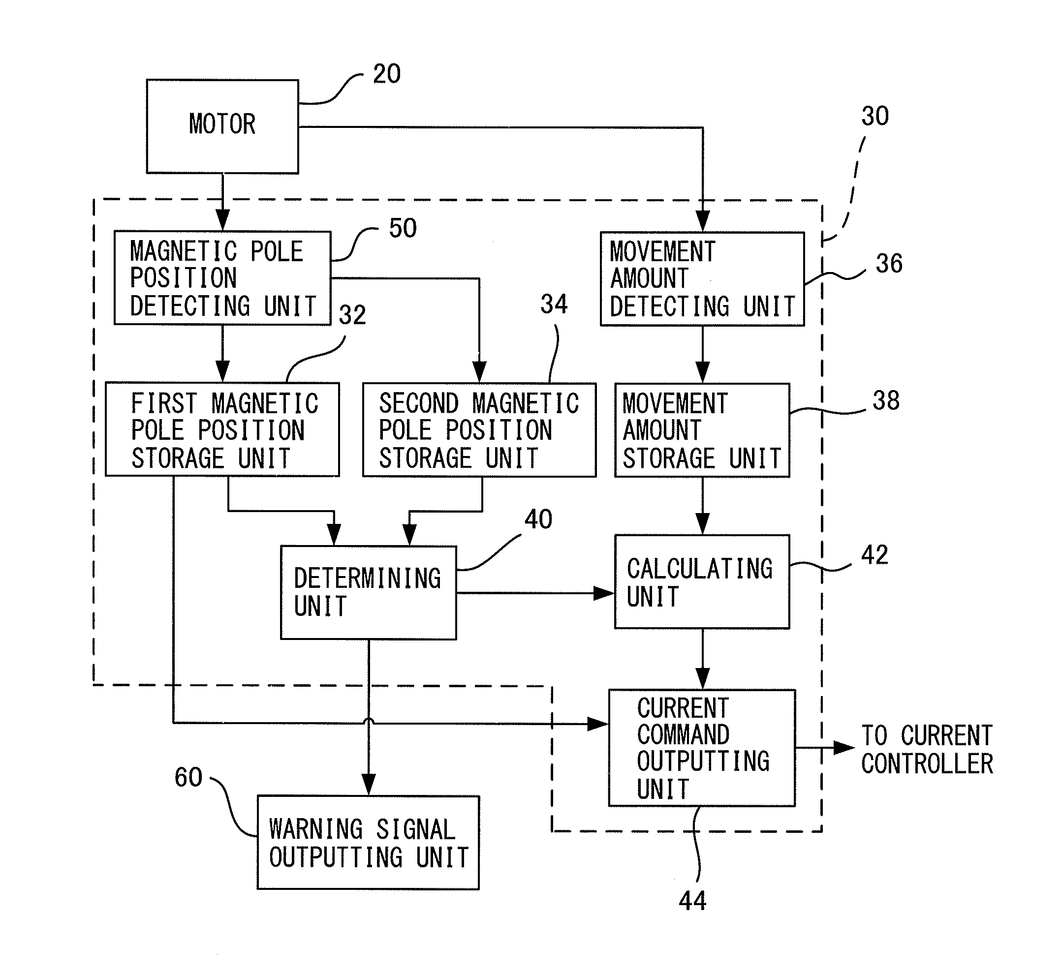
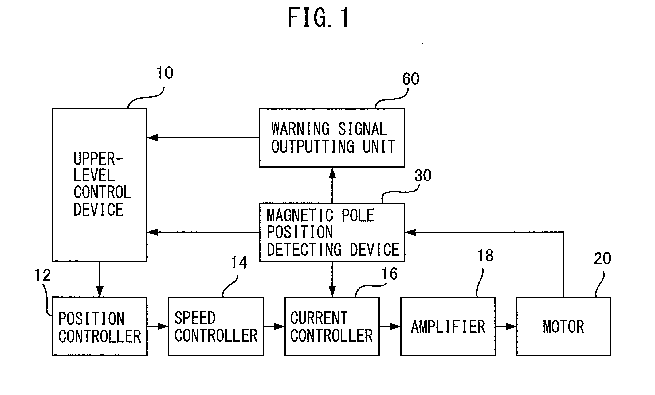
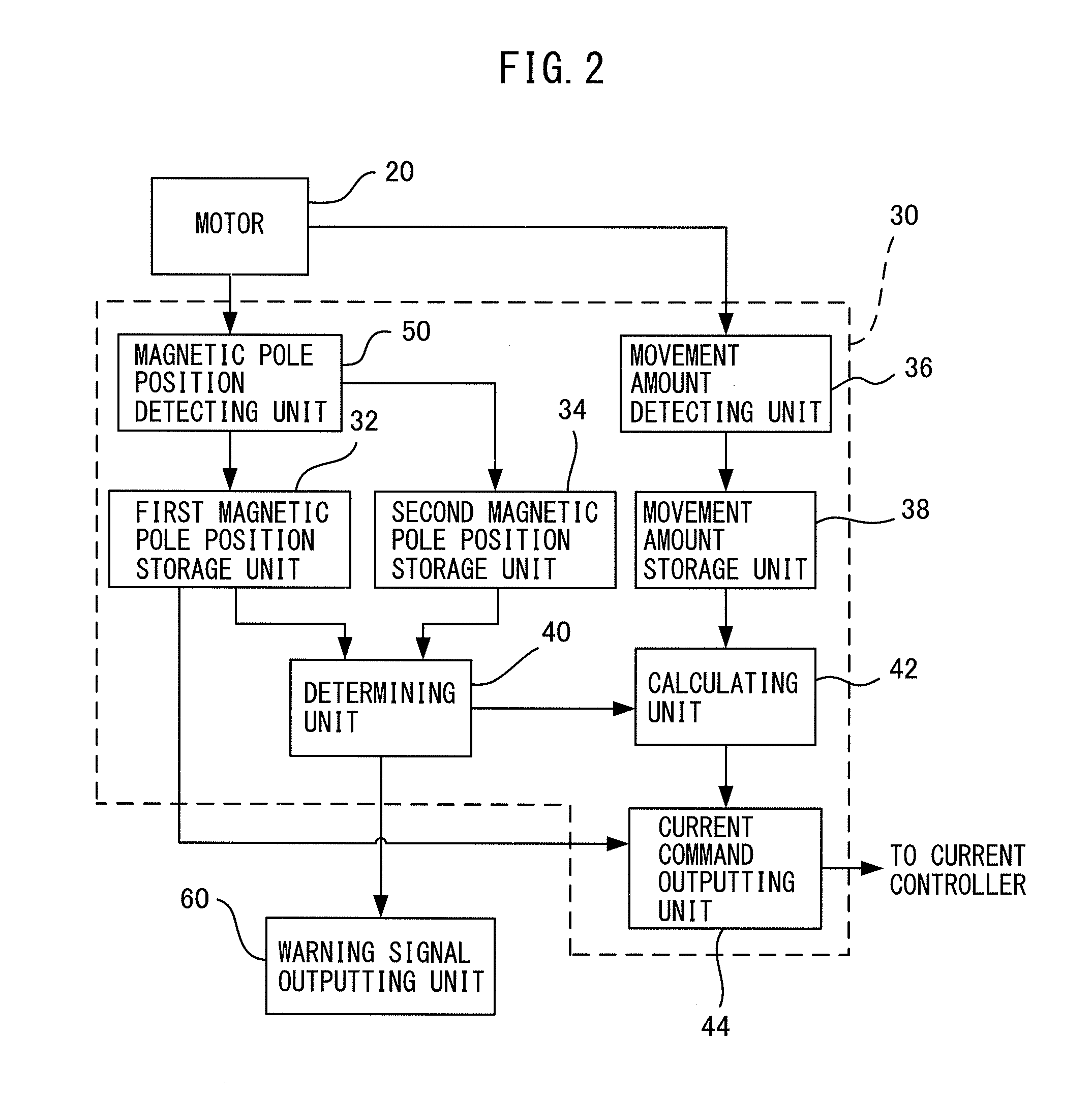
[0018]In the following, embodiments of the present invention will be described with reference to the accompanying drawings. FIG. 1 is a block diagram illustrating a configuration of a control system to which the present invention can be applied. As illustrated in

[0019]FIG. 1, this control system includes an upper-level control device 10, a position controller 12, a speed controller 14, a current controller 16, an amplifier 18, a motor 20, a magnetic pole position detecting device 30, and a warning signal outputting unit 60. The motor 20 is a known permanent-magnet synchronous motor that includes a rotor including permanent magnets, and a stator including coils. The motor 20 is also provided with a sensor that detects movement (a position and a speed) of the rotor is provided. An example of the sensor is an encoder (not illustrated).

[0020]The upper-level control device 10 controls operation of the motor 20 provided in a machine tool or the like. In accordance with a given machining p...


PUM


Abstract

A magnetic pole position detecting device includes a calculating unit for correcting a magnetic pole position detected by a magnetic pole position detecting unit. In this magnetic pole position detecting device, an additional phase is added to the magnetic pole position detected by the magnetic pole position detecting unit, in order to move a rotor. In relation to a movement amount before and after this movement, a movement amount detected by the magnetic pole position detecting unit is compared with a movement amount detected by an encoder. When a difference between them is larger than a predetermined threshold, a process of detecting the magnetic pole position is determined as false detection.

Description

BACKGROUND OF THE INVENTION[0001]1. Field of the Invention[0002]The present invention relates to a magnetic pole position detecting device that detects a magnetic pole position of a rotor in a permanent-magnet synchronous motor.[0003]2. Description of the Related Art[0004]In a permanent-magnet synchronous motor (hereinafter, referred to simply as a motor) that includes a rotor including permanent magnets and that includes a stator including coils, electric currents are applied to the coils in accordance with a magnetic pole position of the rotor so that desired torque can be obtained. For this reason, while the magnetic pole position of the rotor is detected by a sensor such as an encoder, electric currents are applied at an appropriate exciting phase to drive and control the motor.[0005]Accordingly, in such a motor, at the time of starting the motor, position matching between a reference position of the sensor and the magnetic pole position of rotor is performed. A method of detect...

Claims


Application Information

Patent Timeline
IPC IPC(8): H02P6/18H02P23/16H02P23/18H02P27/06
CPCH02P6/18
Inventor SONODA, NAOTOAOCHI, MASATO
Owner FANUC LTD
Why Eureka
Try Eureka