Flow measuring device

a technology of flow measurement and measuring device, which is applied in the direction of measurement device, volume/mass flow measurement, instruments, etc., can solve the problem that the influence of the bottom flow cannot be sufficiently inhibited, and achieve the effect of preventing the reduction of detection accuracy and reducing detection accuracy

Active Publication Date: 2019-04-11
MITSUBISHI ELECTRIC CORP
View PDF2 Cites 1 Cited by
  • Summary
  • Abstract
  • Description
  • Claims
  • Application Information

AI Technical Summary

Benefits of technology

[0020]As described above, an influence of a bottom flow cannot be sufficiently inhibited by using a conventional countermeasure and a method. Therefore, the present invention has been made to solve the above-described problems, and an object of the invention is to provide a flow measuring device in which an influence of a bottom flow can be inhibited and a reduction of detection accuracy can be prevented.
[0021]In a flow measuring device of the present invention, a concave portion, which inhibits a bottom flow which is flowed and inputted from a fit gap between an installing portion of a supporting component and a flow detecting element, is provided at a bottom surface of the installing portion of the supporting component, which is faced to a cavity portion of the flow detecting element.
[0022]According to the flow measuring device of the present invention, even when a bottom flow is flowed and inputted from a fit gap between a flow detecting element and an installing portion of a supporting component, a reduction of a flow velocity of the bottom flow and a flow direction of the bottom flow are controlled, whereby an influence of the bottom flow can be inhibited and a reduction of detection accuracy can be prevented.

Problems solved by technology

As described above, an influence of a bottom flow cannot be sufficiently inhibited by using a conventional countermeasure and a method.

Method used


Image

  • Flow measuring device
  • Flow measuring device
  • Flow measuring device

Examples


embodiment 1

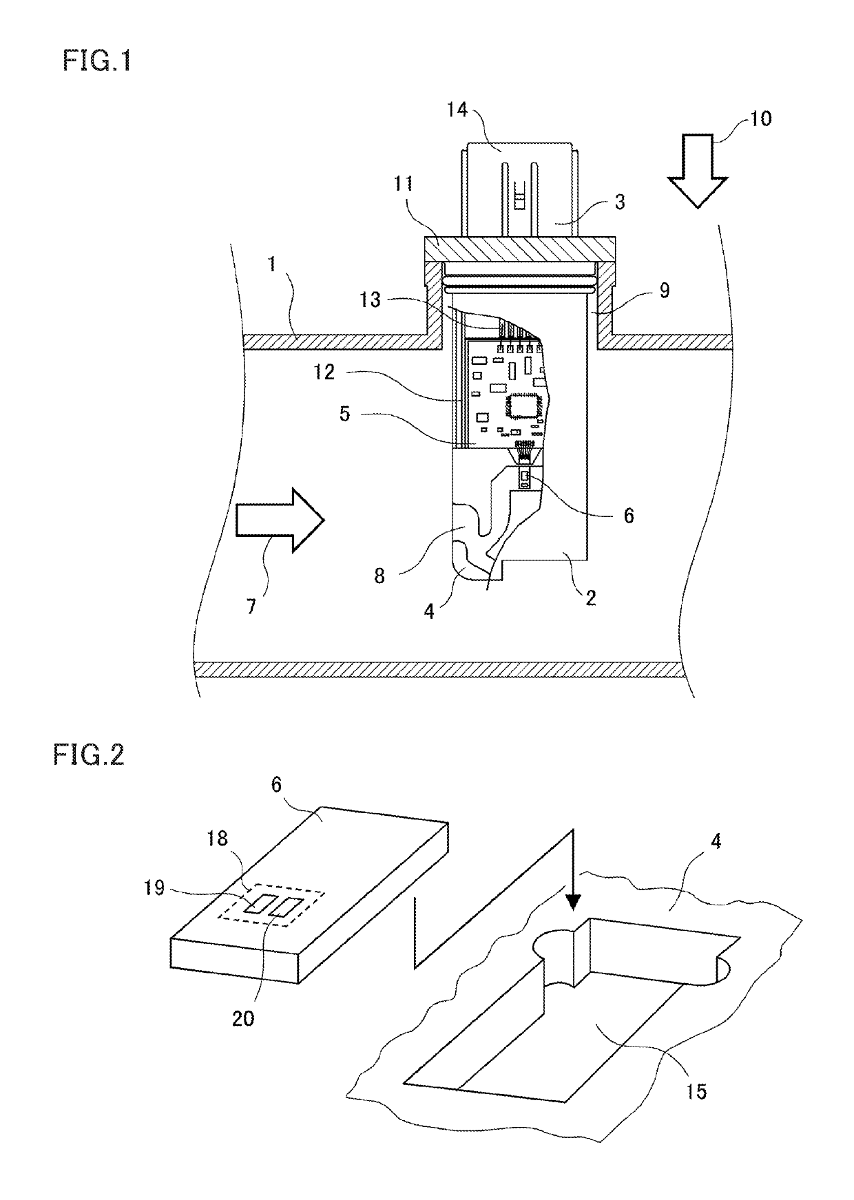
[0064]FIG. 1 is a front view in which a part of a flow measuring device according to Embodiment 1 of the present invention is cut out and indicated.

[0065]The flow measuring device, which is attached to an intake air pipeline 1 which is used as a main passage, is composed of components which are a cover 2, a base 3, a plate 4 which is used as a supporting component, a circuit board 5 which composes a control circuit, and a flow detecting element 6, moreover, the plate 4 is provided at the intake air pipeline 1 (main passage), and the cover 2 and the plate 4 are attached by using an adhesive or the like, whereby a bypass passage 8, which inputs a part of inhalation air 7 which is a measured fluid which is flowed in the intake air pipeline 1 in an arrow direction, is formed. The control circuit, which is composed of the circuit board 5, drives the flow detecting element 6, and the control circuit processes a signal of the flow detecting element 6.

[0066]For example, a PBT resin or the l...

embodiment 2

[0094]In Embodiment 2, a flow measuring device, which can more prevent a reduction of detection accuracy, which is caused by a bottom flow, in comparison with the above-described flow measuring device according to Embodiment 1, will be explained.

[0095]FIG. 20 is a front view which indicates an installing portion 15 which is provided at a plate 4 of the flow measuring device according to Embodiment 2. Moreover, FIG. 21 is a cross-sectional view in which a cross section along “B-B” line in FIG. 20 is indicated, and FIG. 22 is a cross-sectional view in which a cross section along “A-A” line in FIG. 20 is indicated.

[0096]In the flow measuring device according to Embodiment 2, the flow measuring device has a configuration in which a bottom flow inhibitor 28 is coated on the installing portion 15 of the plate 4. In addition, the other configurations according to Embodiment 2 are similar to the configurations according to Embodiment 1, so that an explanation is omitted.

[0097]In the flow me...

embodiment 3

[0100]In Embodiment 3, a flow measuring device, which can more prevent a reduction of detection accuracy, which is caused by a bottom flow, in comparison with the above-described flow measuring device according to Embodiment 1, will be explained.

[0101]FIG. 25 is a front view which indicates an installing portion 15 which is provided at a plate 4 of the flow measuring device according to Embodiment 3. Moreover, FIG. 26 is a cross-sectional view in which a cross section along “B-B” line in FIG. 25 is indicated, and FIG. 27 is a cross-sectional view in which a cross section along “A-A” line in FIG. 25 is indicated.

[0102]In the flow measuring device according to Embodiment 3, in a bottom flow inhibition concave portion 34 which is compared with the bottom flow inhibition concave portion 34 according to Embodiment 1, a taper 37, which is gradually narrowed toward a bottom surface direction of the bottom flow inhibition concave portion 34, is provided. In other words, at the bottom flow i...


PUM


Abstract

Provide a flow measuring device which inhibits a reduction of flow detection accuracy, which is caused by an influence of a bottom flow which is flowed and inputted from a fit gap between a flow detecting element and an installing portion of the flow detecting element. A concave portion, which inhibits an influence of a bottom flow which is flowed and inputted from a fit gap between an installing portion and a flow detecting element, is provided at a bottom surface of the installing portion of a plate which is positioned on a projected area of a cavity of the flow detecting element.

Description

BACKGROUND OF THE INVENTIONField of the Invention[0001]The present invention relates to a flow measuring device, and relates to a device which measures an air mass flow of, for example, an internal combustion engine.Background Art[0002]As a flow measuring device which is mounted at an intake air pipeline of an internal combustion engine and measures a flow of inhalation air, a thermal-type flow measuring device is used.[0003]In a general thermal-type flow measuring device, a measuring passage (hereinafter, referred to as a bypass passage), in which a part of inhalation air is inputted, is formed, and a flow detecting element is disposed in the bypass passage.[0004]In the general thermal-type flow measuring device, the bypass passage is formed in such a way that a plurality of components (mold components are mainly adopted) are fitted, and an installing portion having a concave shape, by which the flow detecting element is mounted, is provided in one component in the plurality of com...

Claims


Application Information

Patent Timeline
Patent Type & Authority Applications(United States)
IPC IPC(8): G01F1/684G01F15/14
CPCG01F1/6842G01F1/6845G01F15/14G01F1/692
Inventor AKAGI, KAZUTOARIYOSHI, YUJIKAWAI, MASAHIROKISHIKAWA, NAOYUKI
Owner MITSUBISHI ELECTRIC CORP
Why Eureka
Try Eureka