Switching power source apparatus

a power source and power supply technology, applied in the direction of electric variable regulation, process and machine control, instruments, etc., can solve the problems of increasing costs and complicated circuit configuration, and achieve the effects of simple circuit configuration, simple circuit configuration, and complicated circuit configuration

Active Publication Date: 2009-04-23
SANKEN ELECTRIC CO LTD
View PDF4 Cites 30 Cited by
  • Summary
  • Abstract
  • Description
  • Claims
  • Application Information

AI Technical Summary

Benefits of technology

[0020]On the other hand, the related art of the Japanese Unexamined Patent Application Publication No. 2005-328589 employs two input voltage detectors, i.e., the first and second low-voltage-operation stop circuits, to complicate circuit configuration and increase costs.
[0021]According to the present invention, a switching power source apparatus that has a simple circuit configuration, is inexpensive, and is capable of correctly detecting an input voltage irrespective of AC ripple voltage superimposed on the input voltage, thereby realizing accurate low-input protection can be provided.

Problems solved by technology

On the other hand, the related art of the Japanese Unexamined Patent Application Publication No. 2005-328589 employs two input voltage detectors, i.e., the first and second low-voltage-operation stop circuits, to complicate circuit configuration and increase costs.

Method used


Image

  • Switching power source apparatus
  • Switching power source apparatus
  • Switching power source apparatus

Examples


first embodiment

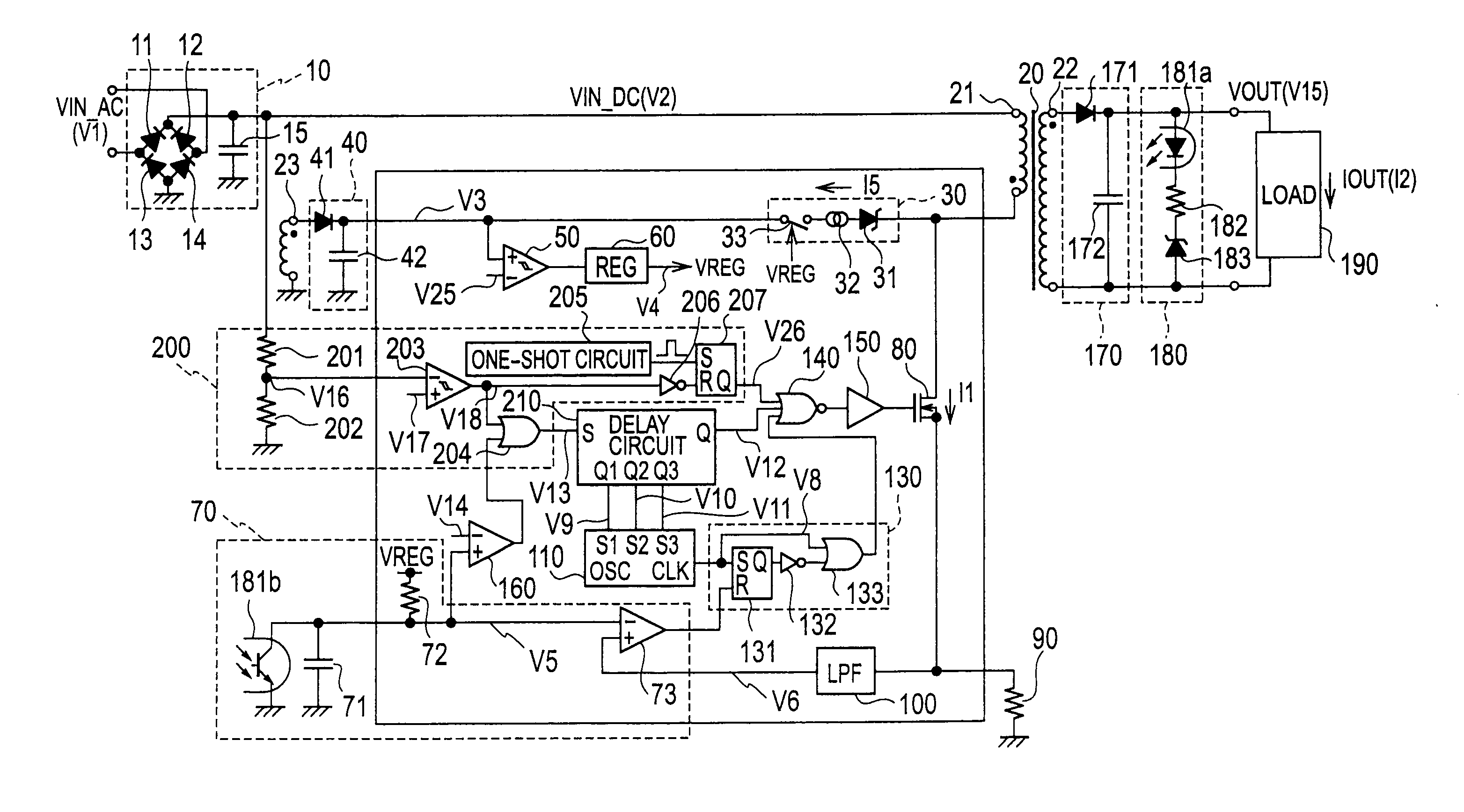
[0037]FIG. 3 is a circuit diagram showing a switching power source apparatus according to the first embodiment of the present invention. The apparatus includes an input rectifying-smoothing circuit 10, a transformer 20, a primary winding 21, a drive winding 23, a starter 30, a rectifying-smoothing circuit 40, a low-voltage-malfunction preventer 50, a reference voltage circuit 60, a feedback controller 70, a switching element 80, a current detecting resistor 90, a low-pass filter (LPF) 100, a first oscillator 110, a PWM controller 130, a NOR gate 140, a driver 150, a comparator 160, a low-input protective controller 200, a delay circuit 210, a rectifying-smoothing circuit 170, an output voltage detector 180, and a load 190.

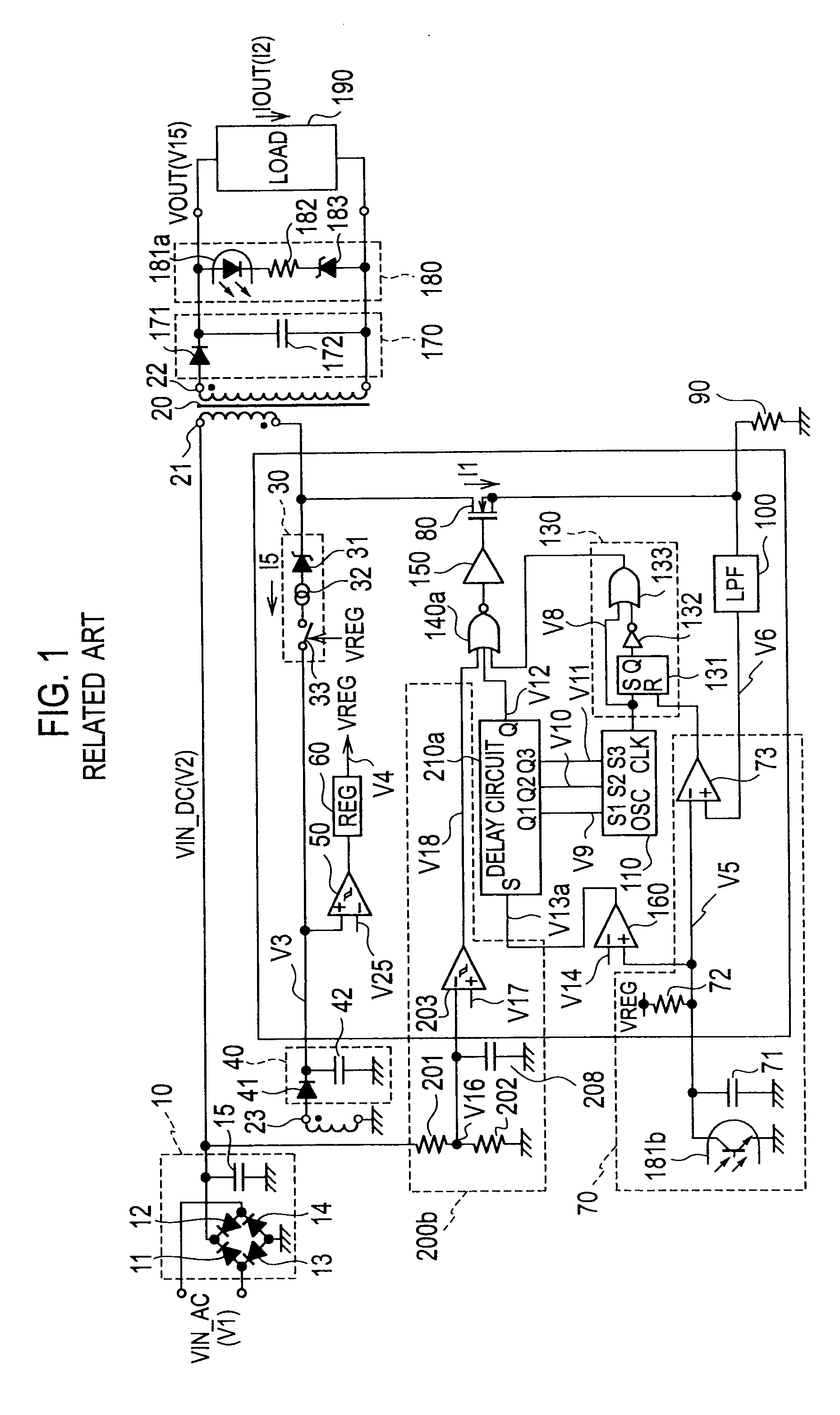
[0038]The first embodiment of FIG. 3 differs from the related art of FIG. 1 in the circuit configuration of the low-input protective controller 200, delay circuit 210, and NOR gate 140.

[0039]Each part of the first embodiment will be explained. The input rectifying-...

second embodiment

[0083]FIG. 9 is a circuit diagram showing a switching power source apparatus according to the second embodiment of the present invention. The second embodiment of FIG. 9 differs from the first embodiment of FIG. 3 in that the second embodiment directly connects an input terminal of a voltage dividing resistor 201 to a voltage terminal of an AC voltage source and a connection point between diodes 12 and 14. The other parts of FIG. 9 are the same as those of FIG. 3, and therefore, are represented with the same reference marks.

[0084]According to the second embodiment of FIG. 9, the voltage dividing resistors 201 and 202 divide an AC voltage and provide a half-wave-rectified voltage to an inverting terminal of a comparator 203 so that the comparator 203 detects a peak value of the AC voltage. This configuration realizes a low-input protecting function like the first embodiment.

[0085]To detect an AC voltage, a power loss of the voltage dividing resistors 201 and 202 according to the seco...

third embodiment

[0086]FIG. 10 is a circuit diagram showing a switching power source apparatus according to the third embodiment of the present invention. The third embodiment of FIG. 10 differs from the second embodiment of FIG. 9 in that the third embodiment connects a diode 240 between a connection point of diodes 12 and 14 and an input terminal of a voltage dividing resistor 201. The other parts of FIG. 10 are the same as those of FIG. 9, and therefore, are represented with the same reference marks.

[0087]According to the third embodiment of FIG. 10, the diode 240 half-wave-rectifies an AC voltage V1 and the voltage dividing resistors 201 and 202 divide the half-wave-rectified voltage to provide a half-wave divided voltage, which is supplied to an inverting terminal of a comparator 203 so that the comparator 203 detects a peak value of the AC voltage. This configuration also realizes a low-input protecting function. Like the second embodiment of FIG. 9, the third embodiment can reduce the standby...


PUM


Abstract

A switching power source apparatus includes a switching element connected through a primary winding of a transformer to a voltage terminal of a DC input voltage, a rectifying-smoothing circuit to rectify and smooth a voltage induced by a secondary winding of the transformer and provide a DC output voltage, a control circuit for controlling ON/OFF of the switching element, and a delay circuit to generate a predetermined delay time. The control circuit detects the DC input voltage, starts a switching operation of the switching element if the DC input voltage has increased to or above a threshold value, and stops the switching operation of the switching element if the DC input voltage is lower than the threshold value and that a period during which the DC input voltage is continuously lower than the threshold value has reached the predetermined delay time.

Description

BACKGROUND OF THE INVENTION[0001]1. Field of the Invention[0002]The present invention relates to a switching power source apparatus that correctly detects a peak value of an AC voltage, and if the AC voltage is too low, stops the switching operation of a switching element to protect the switching element from breakage. Such a breakage may occur during an abnormal test of the switching power source apparatus, such as a brownout test that gradually decreases an AC voltage applied to the switching power source apparatus from a rated voltage and a brown-in test that gradually increases an AC voltage applied to the switching power source apparatus from a low voltage to the rated voltage. The breakage of the switching element may also occur with a poor power source that applies a low voltage to an AC input terminal of the switching power source apparatus, to cause the switching element to excessively increase its ON duty.[0003]2. Description of the Related Art[0004]There are some related ...

Claims


Application Information

Patent Timeline
Patent Type & Authority Applications(United States)
IPC IPC(8): H02M7/217
CPCH02M3/33507H02M1/32
Inventor NAKAMURA, MASARU
Owner SANKEN ELECTRIC CO LTD
Why Eureka
Try Eureka