Intermittent air-generating device

a technology of air generating device and intermittent air, which is applied in the direction of valve operating means/releasing devices, mechanical equipment, servomotors, etc., can solve the problems of increasing production costs, circuit configuration complexity, and production costs accordingly, so as to increase production costs, circuit configuration complexity, and production cost

Active Publication Date: 2022-04-12
SMC CORP
View PDF17 Cites 0 Cited by
  • Summary
  • Abstract
  • Description
  • Claims
  • Application Information

AI Technical Summary

Benefits of technology

[0007]However, the above-described intermittent air generating device includes the pilot type control valve in addition to the pilot type on-off valve, and thus includes two pilot valves in total. This complicates the circuit configuration and increases the number of parts and production costs accordingly.
[0008]A general object of the present invention is to provide an intermittent air generating device with a simple configuration and which can be produced at low cost and is capable of achieving stable performance.
[0014]The body of the switching unit includes the first port to which the compressed air is supplied from the supply source and the third port to which the pilot air is supplied. The valve element is moved by the pilot air to thereby cause the first port and the second port to communicate with each other, whereby the compressed air is output. As a result, the intermittent operation can be stably performed without being affected by pressure drop when the compressed air is supplied to the air device and jetted out.
[0015]Moreover, since the pilot valve driven by the pilot air and the pilot type on-off valve are integrated into one component, the circuit configuration can be simplified, and accordingly the number of parts and production costs can be reduced, compared with conventional intermittent air generating devices.

Problems solved by technology

This complicates the circuit configuration and increases the number of parts and production costs accordingly.

Method used


Image

  • Intermittent air-generating device
  • Intermittent air-generating device
  • Intermittent air-generating device

Examples


first embodiment

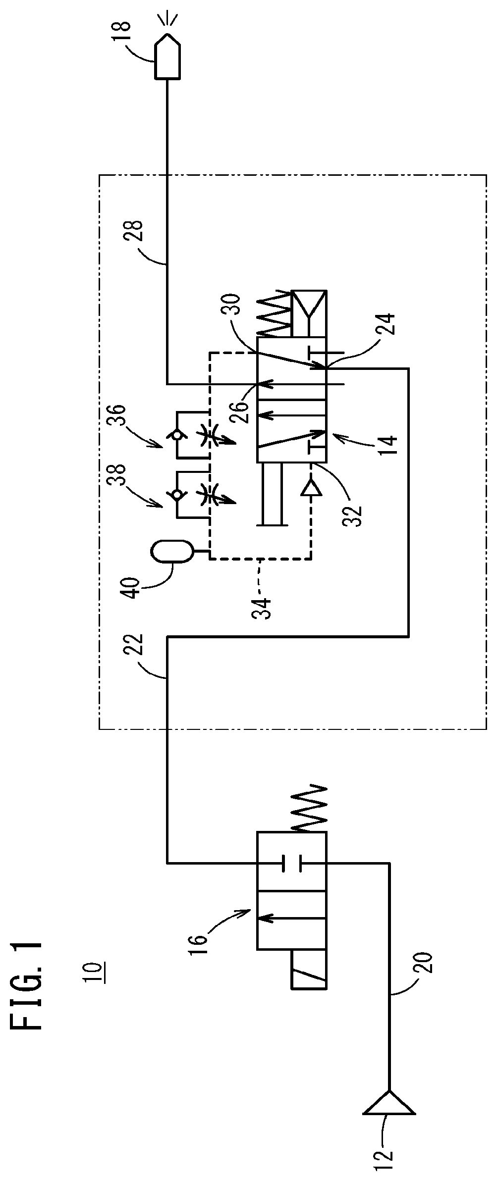
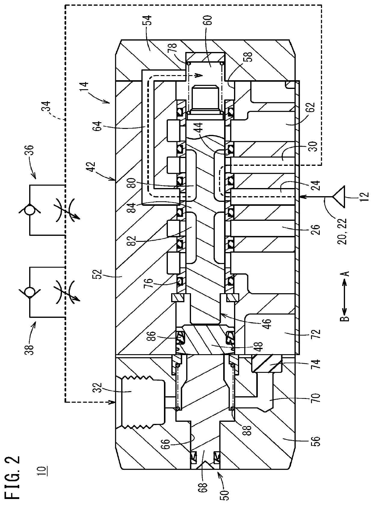
[0047]The intermittent air generating device 10 according to the present invention is basically configured as above. Next, the operations and the operational effects will be described. In the description below, the initial state is defined as a state where the control valve 14 is in the off state and compressed air is not supplied to the air blow gun 18 as illustrated in FIG. 2. First, when the control valve 14 is in an off state as illustrated in FIG. 2, compressed air from the fluid supply source 12 is supplied to the switching valve 16 via the first supply pipe 20. Since the switching valve 16 is in the off state, the compressed air is not supplied to the inlet port 24 of the control valve 14.

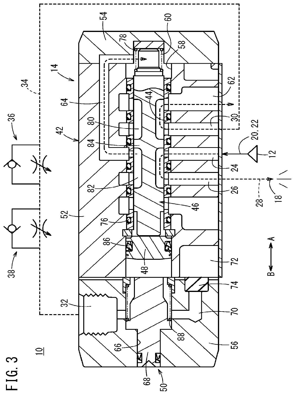
[0048]Next, the switching valve 16 is switched to the on state based on the control signal from the controller (not illustrated), and the compressed air that has been supplied to the first supply pipe 20 is introduced to the inlet port 24 of the control valve 14 via the second supply pipe 22...

second embodiment

[0068]The intermittent air generating device 100 according to the present invention is basically configured as above. Next, the operations and the operational effects will be described.

[0069]In the description below, the initial state is defined as a state where the control valve 102 is in the off state and compressed air is not supplied to the air blow gun 18 as illustrated in FIG. 5.

[0070]First, when the control valve 102 is in the off state as illustrated in FIG. 5, compressed air supplied from the fluid supply source 12 is introduced to the inlet port 24 of the control valve 102 via the first supply pipe 20 while pilot air from the fluid pressure device (not illustrated) is introduced to the external pilot input port 104. At this moment, since the inlet port 24 is closed by the outer circumferential surface of the valve element 46, the compressed air introduced to the inlet port 24 does not flow into the outlet port 26.

[0071]On the other hand, the pilot air flows into the pilot ...


PUM


Abstract

A control valve in an intermittent air-generating device has a five-port valve, the inlet port of which is connected to a fluid supply source and the outlet port is connected to an air-spraying device. As a result of pilot air being supplied to a pilot input port, a valve element moves, and as a result of the inlet port and the outlet port being put in an ON state in which the two are in communication with each other, compressed air is sprayed from the air-spraying device. Meanwhile, as a result of the pilot air being discharged from the pilot input port by way of a discharge port, the valve element moves in the opposite direction and the inlet port and the outlet port are put in an OFF state in which the state of communication between the two is blocked. The ON state and OFF state alternate intermittently.

Description

TECHNICAL FIELD[0001]The present invention relates to, for example, an intermittent air generating device capable of intermittently generating compressed air.BACKGROUND ART[0002]Heretofore, intermittent air generating devices intermittently generating compressed air have been used to, for example, blow the compressed air generated by the intermittent air generating devices against objects such as workpieces via air blow guns in order to remove dust and the like adhering on the objects.[0003]In such an intermittent air generating device, as disclosed in, for example, Japanese Laid-Open Patent Publication No. 2016-075377, one of the outputs from an air pressure source is connected to a pilot type on-off valve, and an output port of the pilot type on-off valve is connected to an air nozzle. On the other hand, the other output from the air pressure source is connected to an inlet port of a pilot type control valve comprised of a 2-port pilot valve and, at the same time, also connected t...

Claims


Application Information

Patent Timeline
Patent Type & Authority Patents(United States)
IPC IPC(8): F16K11/07F15B11/06F15B21/12F16K31/383B05B12/06
CPCB05B12/06F16K11/07F15B11/06F15B21/12F15B2211/30525F16K31/383B05B1/005
Inventor DOI, YOSHITADAOSHIMA, MASAYUKIHASEGAWA, NAOMI
Owner SMC CORP
Why Eureka
Try Eureka