Electronic scanning radar apparatus, received wave direction estimating method, and received wave direction estimating program

a radar and electronic scanning technology, applied in the direction of multi-channel direction-finding systems using radio waves, instruments, measurement devices, etc., can solve the problems of failure peak detection, estimation should be performed, algorithm drawbacks, etc., and achieve high accuracy withou and reduce detection accuracy

Inactive Publication Date: 2012-10-25
HONDA ELESYS CO LTD
View PDF12 Cites 32 Cited by
  • Summary
  • Abstract
  • Description
  • Claims
  • Application Information

AI Technical Summary

Benefits of technology

[0045]Thereby, the azimuth detecting unit determines complex data of a detection beat frequency being a beat frequency in which a presence of a target has been detected, the wave number of a received wave based on a matrix created from the complex data with calculating a DOA of the received wave based on a normal equation being created based on the complex data, and the DOA of the received wave is calculated from the normal equation of a signal subspace based on the determined wave number. Thus, it is possible to provide an electronic scanning radar apparatus and a received wave direction estimating method, which can detect the DOA of the received wave with high accuracy without reducing the detection accuracy.

Problems solved by technology

In addition, Japanese Patent Application JP-A-2009-162688 describes that such algorithms have a drawback in which the estimation should be performed after an appropriate number of arrival waves (received waves) (model order in the case of the AR spectrum estimating method) is set.
On the other hand, in the AR spectrum estimation method, when the number of received waves is much smaller than the number of settled orders and the noise component is a large number, there is an issue which a fail peak may be detected even if the averaging process is performed for the correlation matrix (normal equation) to improve accuracy.
Furthermore, for use as in-vehicle radar, which needs small size and low cost, the configuration of receiving system is required to design for less channel (CH) number, and for a case where the configuration is designed suitable for less channel (CH) number, the number of orders to be set becomes limited.
In addition, even if the CH number of receiving system can be reduced, both setting a great number of orders and establishing a suitable setting in response to the number of signal receiving waves can be insufficient at the same time, because only setting a number of orders is possible for the AR spectrum estimation method (defined as a standard AR spectrum estimation method).
However, these methods require heavy computational load and any of these methods do not assure to provide high accuracy estimation result.

Method used


Image

  • Electronic scanning radar apparatus, received wave direction estimating method, and received wave direction estimating program
  • Electronic scanning radar apparatus, received wave direction estimating method, and received wave direction estimating program
  • Electronic scanning radar apparatus, received wave direction estimating method, and received wave direction estimating program

Examples


first embodiment

[0108]Hereinafter, an electronic scanning radar apparatus (FMCW millimeter wave radar) according to a first embodiment of the invention will be described with reference to the accompanying drawings.

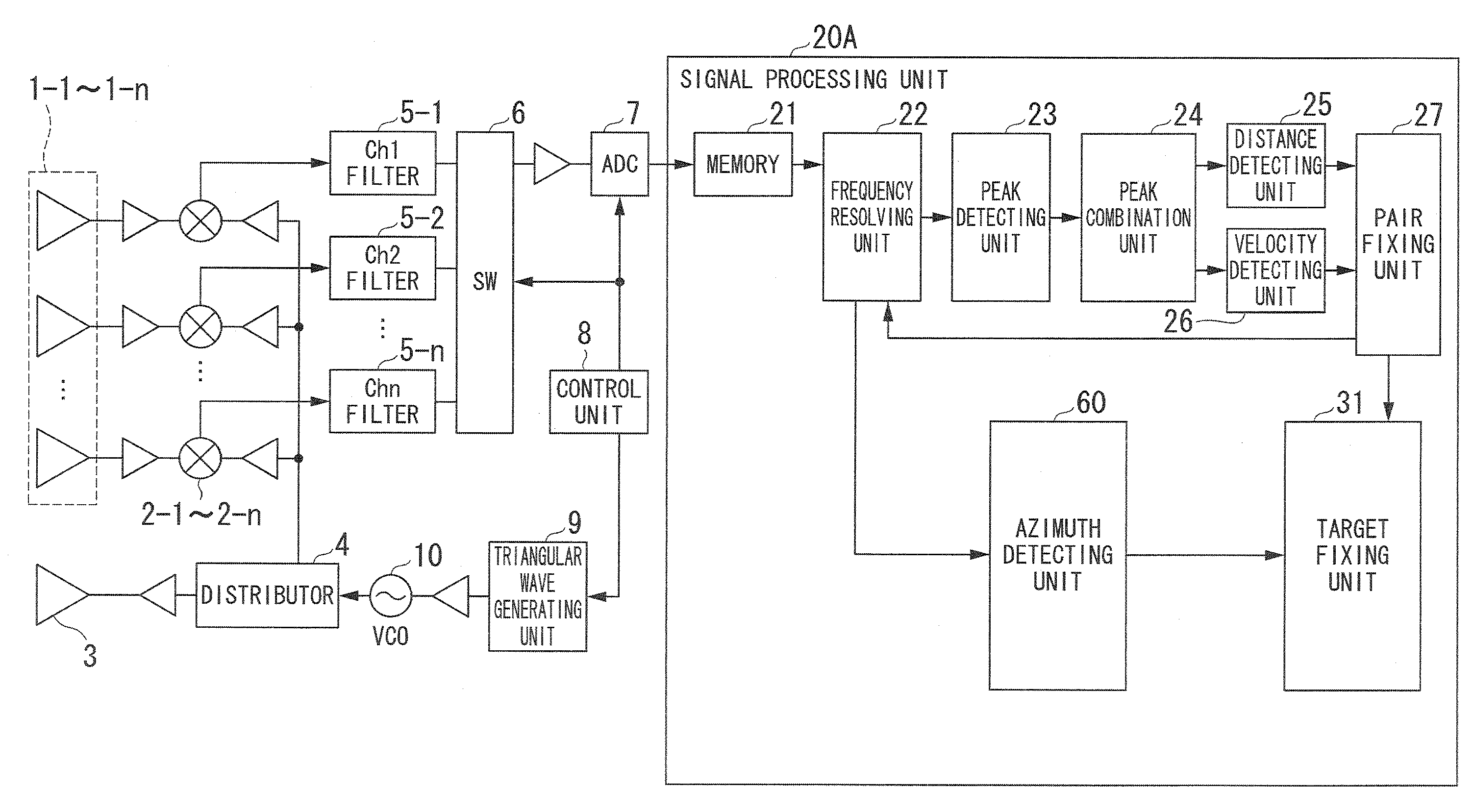
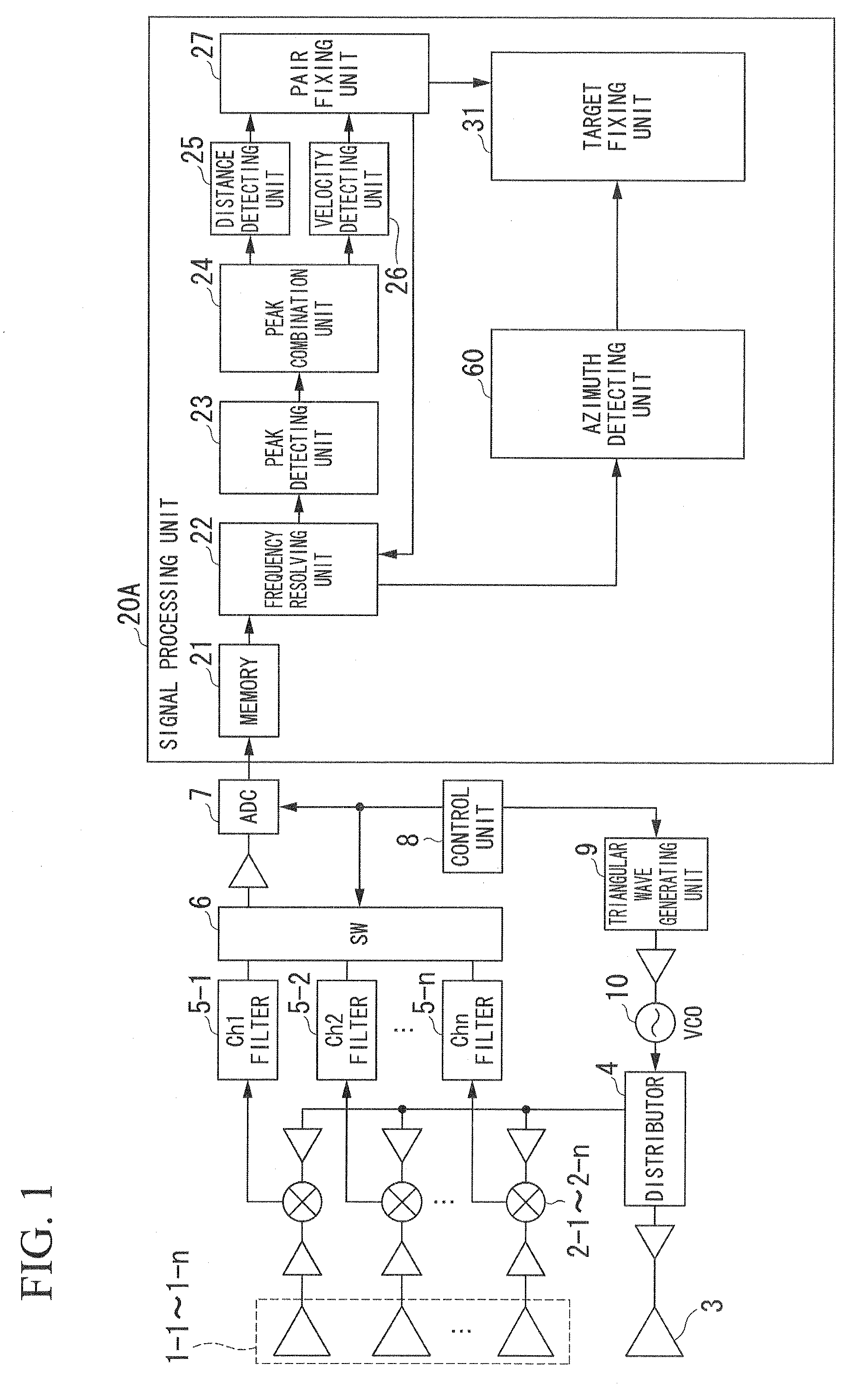
[0109]FIG. 1 is a block diagram illustrating the configuration of the electronic scanning radar apparatus according to the first embodiment.

[0110]In the drawing, the electronic scanning radar apparatus according to the first embodiment includes receiving antennas 1-1 to 1-n, mixers 2-1 to 2-n, a transmitting antenna 3, a distributor 4, filters 5-1 to 5-n, a SW (switch) 6, an ADC (A / D converter) 7, a control unit 8, a triangular wave generating unit 9, a VCO 10, and a signal processing unit 20A.

[0111]The signal processing unit 20A includes a memory 21, a frequency resolving unit 22, a peak detecting unit 23, a peak combining unit 24, a distance detecting unit 25, a velocity detecting unit 26, a pair fixing unit 27, a target fixing unit 31, and an azimuth detecting unit 60. The azimuth dete...

second embodiment

[0248]An electronic scanning radar apparatus according to a second embodiment of the present invention will be described below with reference to FIG. 15.

[0249]FIG. 15 is a block diagram illustrating the configuration of the electronic scanning radar apparatus in the second embodiment.

[0250]A signal processing unit 20B in the second embodiment performs the azimuth estimating process using a high resolution algorithm, similarly to the first embodiment. The same elements as the first embodiment shown in FIG. 1 will be referred by the same reference symbols and the following description will be centered on the differences from the first embodiment.

[0251]The frequency resolving unit 22B of the signal processing unit 20B converts the beat signals of the ascending region and the descending region for each antenna into complex data and outputs the frequency point indicating the beat frequencies thereof and the complex data to the frequency resolving unit 22B.

[0252]The frequency resolving un...

third embodiment

[0262]An electronic scanning radar apparatus according to a third embodiment of the invention will be described below with reference to FIG. 17.

[0263]FIG. 17 is a block diagram illustrating the configuration of the electronic scanning radar apparatus in accordance with the third embodiment.

[0264]A signal processing unit 20C of the third embodiment performs an azimuth estimating process first using a DBF (Digital Beam Forming) with a resolution lower than that of the high resolution algorithm such as the AR spectrum estimating process and then performs the azimuth estimating process using the high-resolution algorithm including the AR spectrum estimating process using the AR coefficient, unlike the first embodiment. The same elements as the first embodiment shown in FIG. 1 will be referenced by the same reference symbols and the following description will be centered on the differences from the first embodiment.

[0265]As shown in the drawing, the third embodiment is different from the...


PUM


Abstract

An electronic scanning radar apparatus in accordance with an embodiment of the present invention, a frequency resolving unit resolves beat signals into beat frequencies having a predetermined frequency bandwidth and calculates complex data based on the resolved beat signals for each beat frequency. An azimuth calculating unit estimates a number of received waves based on eigenvalues of a matrix being part of a primary normal equation having complex data as elements calculated from the beat signals, creates coefficients calculated as a solution of a secondary normal equation of a signal subspace created based on eigenvalues and eigenvectors corresponding to the number of the estimated waves, and calculates a DOA of a received wave based on the created coefficients.

Description

CROSS REFERENCE TO RELATED APPLICATIONS[0001]Priority is claimed on Japanese Patent Application No. 2010-236672, filed Oct. 21, 2010, the content of which is incorporated herein by reference.BACKGROUND OF THE INVENTION[0002]1. Field of the Invention[0003]The present invention relates to an electronic scanning radar apparatus and a received wave direction estimating method, which can detect a target using a reflected wave from the target in response to a transmitted wave and which can be suitably used for a vehicle, and a received wave direction estimating program used therein.[0004]2. Description of Related Art[0005]Electronic scanning type radars such as an FMCW (Frequency Modulated Continuous Wave) radar, a multi-frequency CW (Continuous Wave) radar, and a pulse radar have been known for some time.[0006]In the radars, an arrival wave direction estimating method of an array antenna is used as a technique of detecting an arrival wave (or a received wave) from a target (a reflecting ...

Claims


Application Information

Patent Timeline
Patent Type & Authority Applications(United States)
IPC IPC(8): G01S13/06G01S13/931
CPCG01S3/74G01S13/931G01S13/584G01S13/345
Inventor KANAMOTO, JUNJI
Owner HONDA ELESYS CO LTD
Why Eureka
Try Eureka