Mounting hardware
Active Publication Date: 2013-12-19
THE HILLMAN GRP INC
7 Cites 23 Cited by
AI-Extracted Technical Summary
Problems solved by technology
These options can be quite expensive, and thus are beyond the reach of most projects.
Additionally, working with such connectors can require special skills and equipment, thus placing use and installation of architect...
Abstract
A hardware apparatus includes a base portion formed by a disc-shaped base plate and a cylindrical member. The cylindrical member includes a first threaded surface. The disc-shaped base plate includes a first opening and the cylindrical member includes a second opening, with the first and second openings being concentric. The hardware apparatus further includes a cap portion including a second threaded surface. The cap portion is attachable to said base portion through engagement of the first and second threaded surfaces. In one implementation, the first threaded surface is an outer surface and the second threaded surface is an inner surface. In an alternative implementation, the second threaded surface is an outer surface and the first threaded. surface is an inner surface.
Application Domain
NutsScrews
Technology Topic
EngineeringMechanical engineering
Image
Examples
- Experimental program(1)
Example
DETAILED DESCRIPTION OF THE DRAWINGS
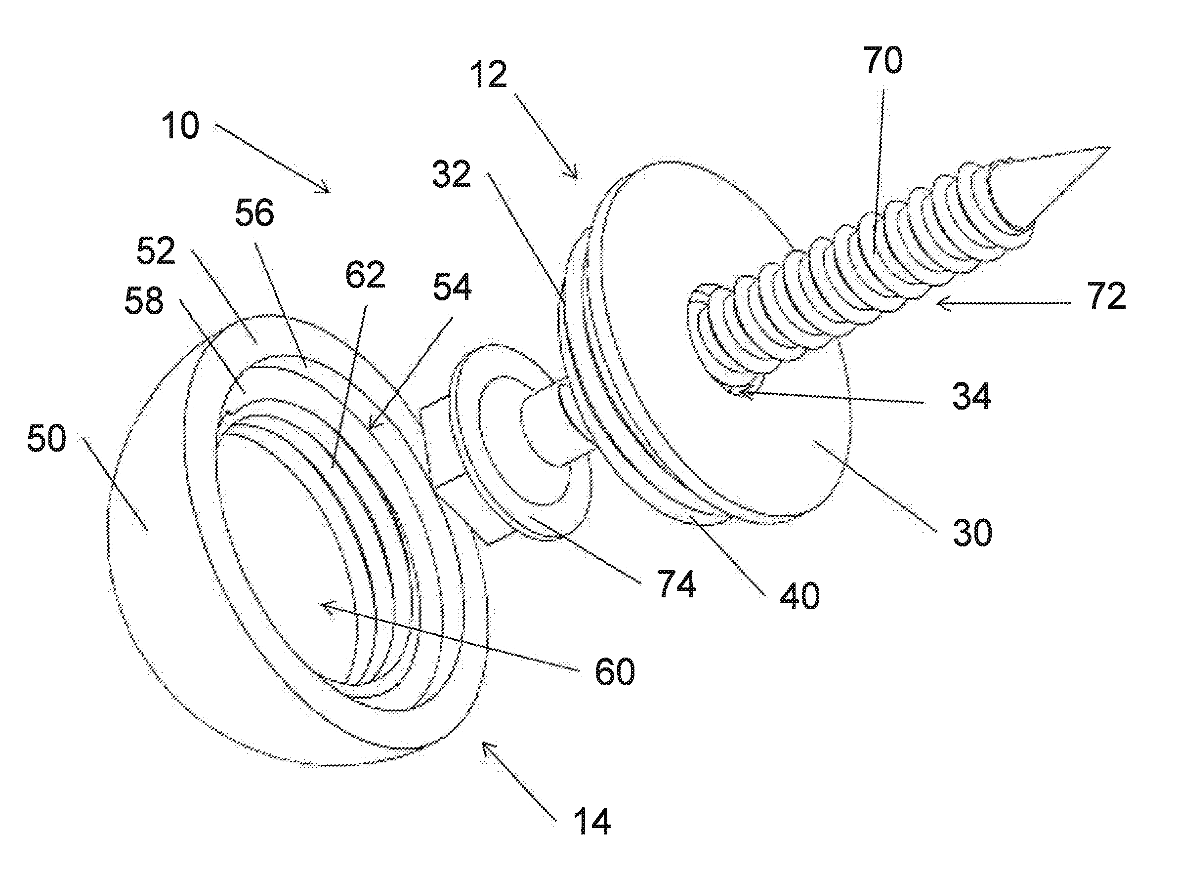
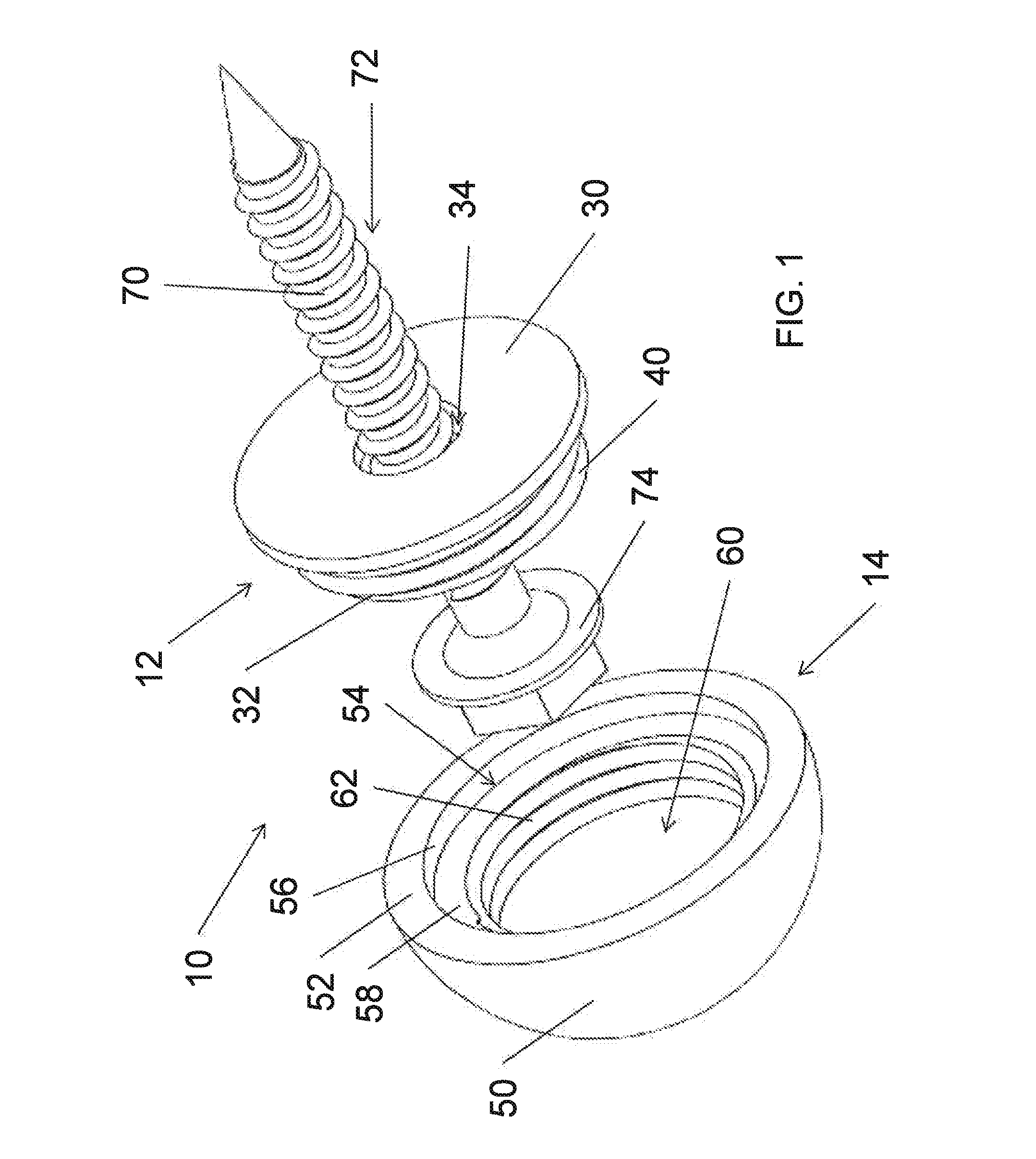
[0025]Reference is now made to FIG. 1 which illustrates an exploded perspective view of a rivet, nail or pin connector 10. The connector 10 comprises a base portion 12 and a cap portion 14. An outer surface of the base portion 12 is threaded. An inner surface of the cap portion 14 is correspondingly threaded. Thus, the cap portion 14 may be attached to the base portion 12 through the threaded interconnection. In this configuration, the base portion 12 comprises a male body member of the assembly and the cap portion 14 comprises a female body member.
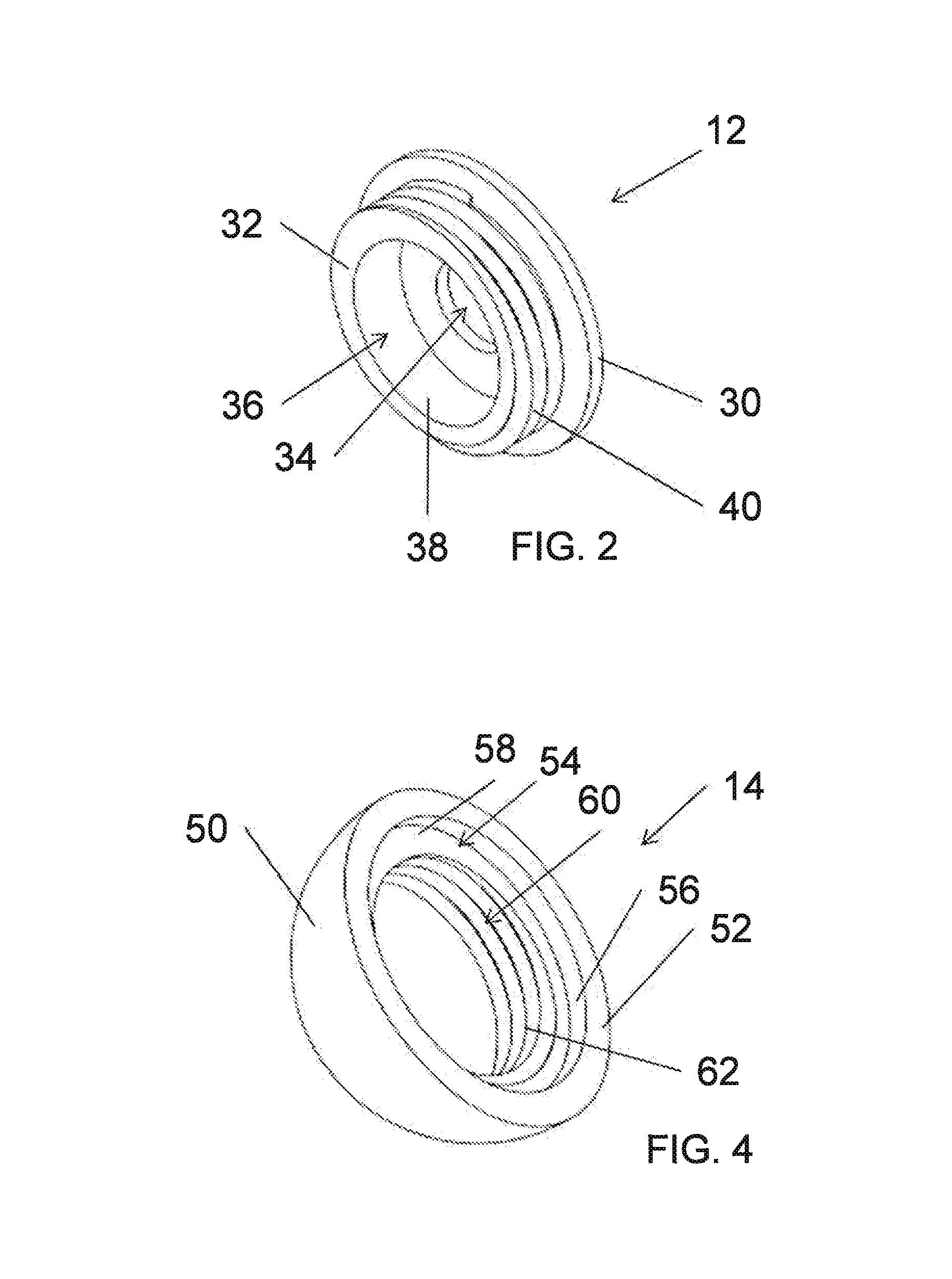
[0026]Reference is now additionally made to FIG. 2 which illustrates a perspective view of the base portion 12 and FIG. 3 which illustrates a cross-sectional view of the base portion 12. The base portion 12 comprises a disc-shaped base plate 30. A cylindrical member 32 is mounted to the base plate 30. The cylindrical member 32 is preferably centered on the base plate 30. The base plate 30 includes an opening 34 extending there through. The cylindrical member 32 includes an opening 36 coaxially aligned with the opening 34. The cylindrical member 32 accordingly has an inner sidewall 38 and an outer sidewall 40. The outer sidewall 40 is threaded. The inner sidewall 38 is smooth.
[0027]Reference is now additionally made to FIG. 4 which illustrates a perspective view of the cap portion 14 and FIG. 5 which illustrates a cross-sectional view of the cap portion 14. The cap portion 14 has a domed outer surface 50 and a flat base surface 52. The domed outer surface 50 is sized and shaped to imitate the head of a rivet, nail or pin. The domed outer surface 50 may have a smooth finish. Alternatively, and perhaps preferably, the domed outer surface 50 may have a textured surface, for example with a texture that is dimpled to provide the look of a hammered or distressed surface. A first aperture 54 is formed in the base surface 52. The first aperture 54 is cylindrical and has a side wall 56. The aperture 54 is sized and shaped to receive the base plate 30 of the base portion 12 (i.e., its diameter is slightly larger than the diameter of the base plate 30 and its depth is about equal to a thickness of the base plate 30). A bottom of the first aperture 54 is defined by a ledge 58. A second aperture 60 is also formed, this time in the ledge 58, wherein the second aperture 60 is coaxial with the first aperture 54. The second aperture 60 is cylindrical and has a side wall 62. The sidewall 62 is threaded to matingly correspond with the threaded outer sidewall 40 of the base portion 12. The second aperture 60 has a depth equal to or, or more preferably exceeding a height of the cylindrical member 32.
[0028]Reference is once again made to FIG. 1. The opening 34 in the base plate 30 of the base portion 12 is sized to permit passage there through of a shaft 70 of a mounting device 72 (such as a screw or bolt). The opening 36 (FIGS. 2 and 3) in. the cylindrical member 32 of the base portion 12 is sized to permit reception of a head portion 74 of the mounting device 72. Advantageously, the user is not limited in selection of the mounting device 72. No limit on mounting hardware length, size or grade exists. So, if used in an ornamental manner, the user may choose a lower length, size or grade mounting device 72. However, if used in a structural manner the user may instead select a higher length, size or grade mounting device 72. The connector 10 is accordingly useful over a wide range of uses from purely ornamental to fully structural (where such structural use is augmented by the ornamental features of the cap portion).
[0029]To install the connector 10, the base portion 12 is positioned on a mounting member at a desired mounting location. The mounting device 72 is driven into the mounting member through the opening 34 in the base plate 30 until the head portion 74 rests against the base plate 30. The cap portion 14 is then attached to the base portion 12 by engaging the threaded sidewall 62 of the cap portion 14 to threaded outer sidewall 40 of the base portion 12. The cap portion 14 is rotated to tighten the cap portion 14 into a secured position on the base portion 12 which hides the base plate 30 within the first aperture 54, leaving the cap portion 14 with its domed outer surface 50 exposed. The resulting assembly thus imitates an architectural hardware component of the rivet, nail or pin connector type. Advantageously, the installation solely requires the use of a conventional mounting device 72 (for example, screw or bolt) and thus does not require specific installation expertise or tools. The connector 10 may solely provide a decorative feature as installed. Alternatively, through proper selection of the mounting device 72, the connector 10 may additionally serve as a structural component.
[0030]Reference is now made to FIG. 6 which illustrates an exploded perspective view of a nut/bolt/washer connector 110. The connector 110 comprises a base portion 112 and a cap portion 114. An inner surface of the base portion 112 is threaded. An outer surface of the cap portion 114 is correspondingly threaded. Thus, the cap portion 114 may be attached to the base portion 112 through the threaded interconnection. In this configuration, the base portion 112 comprises a female body member of the assembly and the cap portion 114 comprises a male body member.
[0031]Reference is now additionally made to FIG. 7 which illustrates an exploded perspective view of the base portion 112 and FIG. 8 which illustrates a cross-sectional view of the (assembled) base portion 112. The base portion 112 comprises a disc-shaped base plate 130. A cylindrical member 132 is mounted to the base plate 130 (this is not shown in the exploded view of FIG. 7, see FIG. 8). The cylindrical member 132 is preferably centered on the base plate 130. The base plate 130 includes an opening 134 extending there through. The cylindrical member 132 includes opening 136 coaxially aligned with the opening 134. The cylindrical member 132 accordingly has an inner sidewall 138 and an outer sidewall 140. The inner sidewall 138 is threaded. The outer sidewall 140 is sized and shaped to imitate a hexagonal nut (or bolt head), with the disc-shaped base plate 130 sized and shaped relative thereto to imitate a washer.
[0032]Indeed, the base portion 112 can easily be fabricated from off-the-shelf components. The disc-shaped base plate 130 may be a standard steel hardware washer and the cylindrical member 132 may be a standard steel hex nut. The hex nut may be welded to the washer with a concentric configuration.
[0033]Reference is now additionally made to FIG. 9 which illustrates a perspective view of the cap portion 114 and FIG. 10 which illustrates a side view of the cap portion 114. The cap portion 114 has a flat outer surface 150 and a flat base surface 152. The flat outer surface 150 further includes an opening 154 having a hexagonal shape sized to mate with a standard size Allen wrench or other tool. The opening 154 is optional. The cap portion 114 further includes a cylindrical outer surface 156 extending between the flat outer surface 150 and the flat base surface 152. The cylindrical outer surface 156 is threaded to matingly correspond with the threaded inner sidewall 138 of the base portion 112.
[0034]The cap portion 114 may comprise, for example, a steel set screw.
[0035]Reference is once again made to FIG. 6. The opening 134 in the base plate 130 of the base portion 112 is sized to permit passage there through of a shaft of a mounting device (such as a screw or bolt) like that shown in FIG. 1. The opening 136 (FIGS. 7 and 8) in the cylindrical member 132 of the base portion 112 is sized to permit reception of a head portion of the mounting device as well as receive the cap portion 114. Advantageously, the user is not limited in selection of the mounting device. No limit on mounting hardware length, size or grade exists. So, if used in an ornamental manner, the user may choose a lower length, size or grade mounting device. However, if used in a structural manner the user may instead select a higher length, size or grade mounting device. The connector 110 is accordingly useful over a wide range of uses from purely ornamental to fully structural (where such structural use is augmented by the ornamental features of the base portion and cap portion).
[0036]To install the connector 110, the base portion 112 is positioned on a mounting member at a desired mounting location. The mounting device (reference 72 of FIG. 1) is driven into the mounting member through the opening 134 in the base plate 130 until the head portion 74 (see, FIG. 1) rests against the base plate 130. The cap portion 114 is then attached to the base portion 112 by engaging the threaded outer sidewall 156 of the cap portion 114 to threaded inner sidewall 138 of the base portion 112. The cap portion 114 is rotated to tighten the cap portion 114 into a secured position on the base portion 112. The opening 154 may be advantageously used during the tightening operation to receive an assembly tool such as an Allen wrench. Preferably, the cap portion 114 is tightened until the flat outer surface 150 substantially flush with a top surface 162 of the base portion 112 (see, FIG. 11). The resulting assembly thus imitates an architectural hardware component of the nut/bolt/washer connector type. Advantageously, the installation solely requires the use of a conventional mounting device (for example, screw or bolt) and thus does not require specific installation expertise or tools. The connector 110 may solely provide a decorative feature as installed, Alternatively, through proper selection of the mounting device 72, the connector 110 may additionally serve as a structural component.
[0037]Those skilled in the art recognize that with improvements in construction materials, many installations will no longer require beams or other support members. Nonetheless, the architectural design may require the presence of such beams or members even where they are not structurally required (for example, are not load bearing). It is common in such installations to install faux beams or members, for example, made or foam or other lightweight non-structurally graded materials, that are aesthetically treated through painting and other techniques to look like a real beam or member. To complete the illusion that these faux beams or members are real, it is important that the proper supporting hardware be used (such as rivets, pins, nut/bolt/washers, etc.), The connectors 10 and 110 as discussed herein provide an effective means for adding supporting hardware connectors of a proper style and size. An advantage of the connectors 10 and 110 over prior art hardware is that the mounting device 72 is selectable at user option in accordance with the given application. Thus, the mounting device 72 may chosen for a tack application of the connector 10 or 110, or alternatively chosen for a more structural application (such as for retaining the faux beam or member to a wall stud).
[0038]Although preferred embodiments of the method and apparatus of the present invention have been illustrated in the accompanying Drawings and described in the foregoing Detailed Description, it will be understood that the invention is not limited to the embodiments disclosed, but is capable of numerous rearrangements, modifications and substitutions without departing from the spirit of the invention as set forth and defined by the following claims.
PUM


Description & Claims & Application Information
We can also present the details of the Description, Claims and Application information to help users get a comprehensive understanding of the technical details of the patent, such as background art, summary of invention, brief description of drawings, description of embodiments, and other original content. On the other hand, users can also determine the specific scope of protection of the technology through the list of claims; as well as understand the changes in the life cycle of the technology with the presentation of the patent timeline. Login to view more.