Electrohydrodynamic (EHD) air mover configuration with flow path expansion and/or spreading for improved ozone catalysis

a technology of electrohydrodynamic and air mover, which is applied in the field of electrohydrodynamic air mover, can solve the problems of mechanical air mover being incompatible with, or unacceptably limit, the design, scale or form factor of a particular design, and reducing so as to improve the efficiency of air movement. , the effect of enhancing heat exchang

Inactive Publication Date: 2013-12-26
PANASONIC INTELLECTUAL PROPERTY MANAGEMENT CO LTD
View PDF0 Cites 5 Cited by
  • Summary
  • Abstract
  • Description
  • Claims
  • Application Information

AI Technical Summary

Problems solved by technology

However, in some applications and devices, mechanical air mover operation may result in undesirable levels of noise or vibration that may degrade the user experience.
In some cases, physical scale or flow paths that would otherwise be necessary to accommodate a mechanical air mover may be incompatible with, or unacceptably limit, the design, scale or form factor of a particular design.
Worse still, at the extremely thin device form factors popular in certain consumer electronics (e.g., laptops, pad-type computers, televisions, smartphones, book readers and media players), mechanical air mover designs (if even accommodatable) tend to exhibit poor cooling efficiencies.
As a result, battery life may be adversely affected or, as a practical matter, device performance throttled to a level compatible with passive cooling.
For example, it has been discovered that while thermal management systems based on mechanically forced air flow tend to perform best when the highly turbulent outflow of a fan or blower motivates large volumes of air per unit time over heat transfer surfaces with small ΔT (change in temperature), such design goals and operating characteristics may not transfer well to designs in which an EHD air mover is, instead, employed.
Indeed, it has been discovered that a typical design goal of thermal management systems based on mechanically forced air flow, i.e., that flow cross-sections of the fan or blower be sized to match that of a heat sink, may not be desirable for designs in which an EHD air mover motivates flow.
In contrast, such a design would generally be disfavored for conventional mechanical air mover-based systems.
Again, such variations would generally be disfavored, and indeed unnecessary, for conventional mechanical air mover-based systems in which airflow is already highly turbulent.

Method used


Image

  • Electrohydrodynamic (EHD) air mover configuration with flow path expansion and/or spreading for improved ozone catalysis
  • Electrohydrodynamic (EHD) air mover configuration with flow path expansion and/or spreading for improved ozone catalysis
  • Electrohydrodynamic (EHD) air mover configuration with flow path expansion and/or spreading for improved ozone catalysis

Examples


Embodiment Construction

)

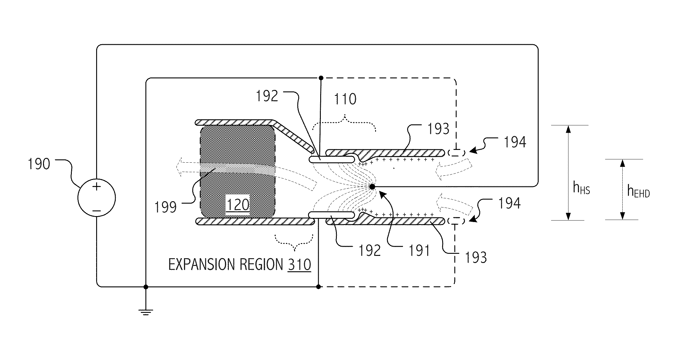
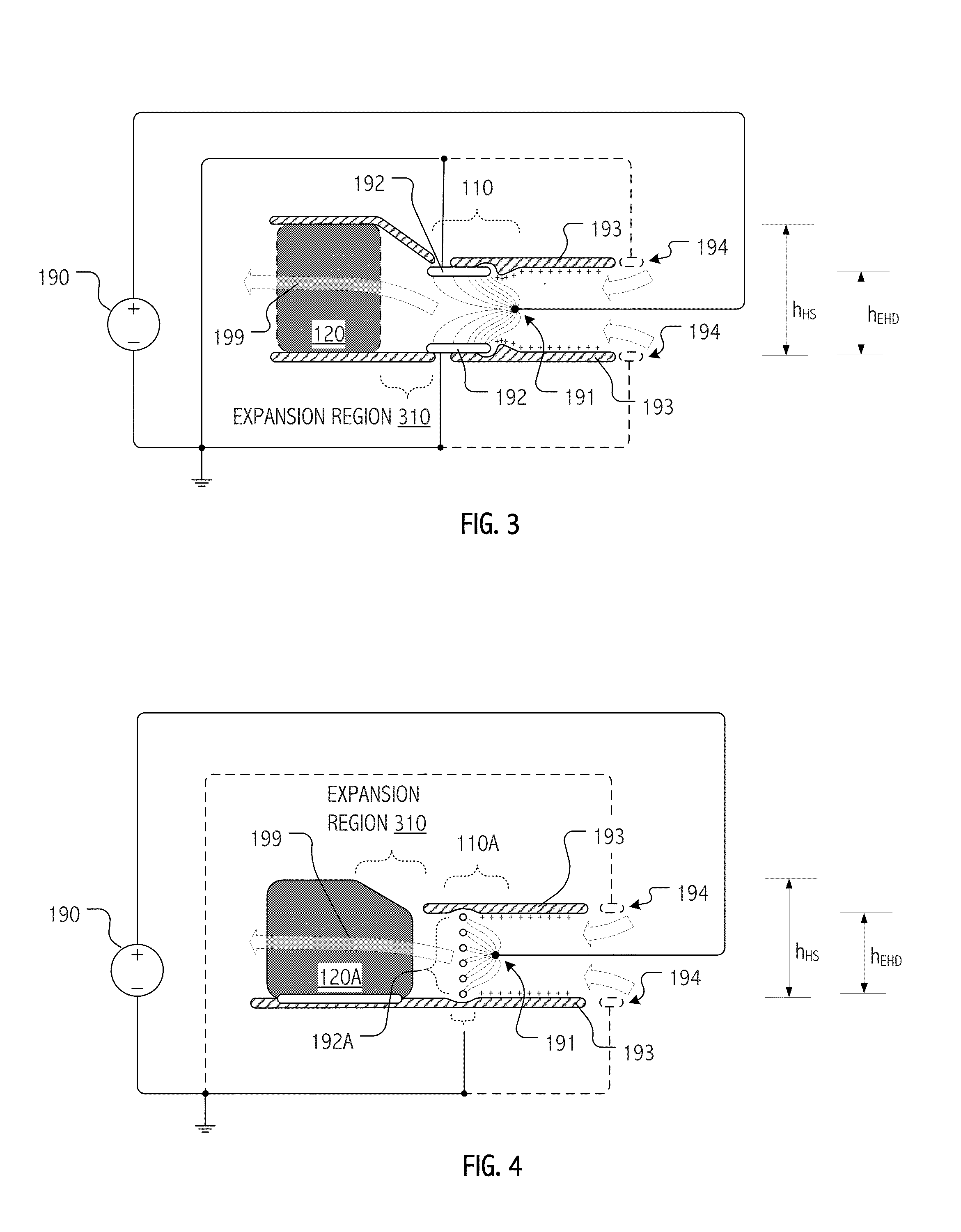
[0037]As will be appreciated, many of the designs and techniques described herein have particular applicability to the thermal management challenges of densely-packed devices and small form-factors typical of modern consumer electronics. Indeed, some of the EHD fluid / air mover designs and techniques described herein facilitate active thermal management in electronics whose thinness or industrial design precludes or limits the viability of mechanical air movers such as fans, blowers, etc. In some embodiments, such EHD fluid / air movers may be fully integrated in an operational system such as a pad-type or laptop computer, a projector or video display device, a set-top box, etc. In other embodiments, such EHD fluid / air movers may take the form of subassemblies or enclosures adapted for use in providing such systems with EHD motivated flows.

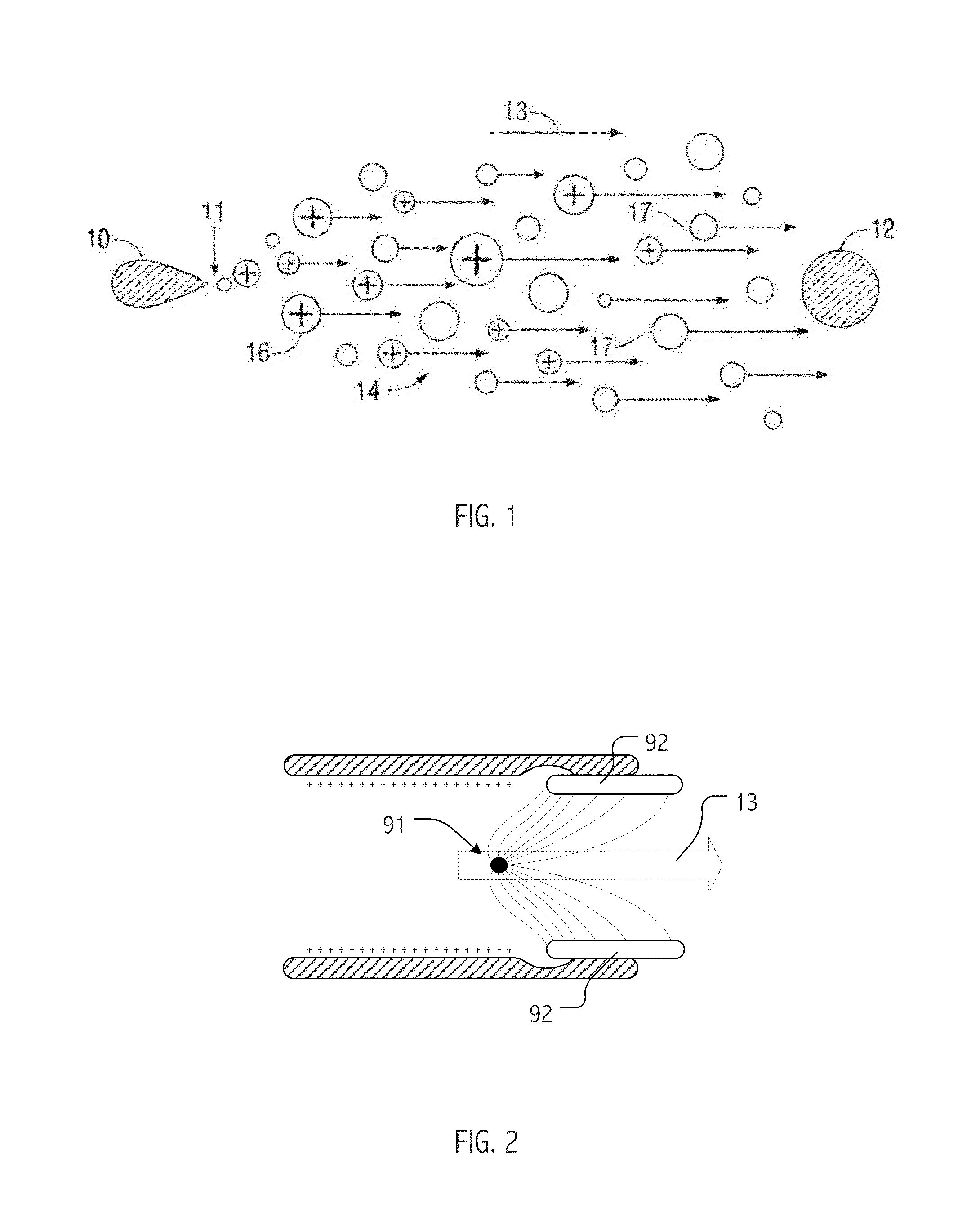
[0038]In general, a variety of scales, geometries and other design variations are envisioned for emitter and / or collector electrodes (as well as ot...


PUM

PropertyMeasurementUnit
diameteraaaaaaaaaa
length:heightaaaaaaaaaa
transit timeaaaaaaaaaa

Abstract

Provision of an expansion region (e.g., a flow path with increasing cross-section downstream of the EHD air mover) can provide operational benefits in EHD air mover-based thermal management systems. In contrast, such a design would generally be disfavored for conventional mechanical air mover-based systems. In some cases, an expansion chamber or volume may be provided between the EHD air mover and heat transfer surfaces. In some cases, expansion of the flow cross-section may be provided (at least in part) within the heat transfer surface volume itself. In some cases, leading surfaces of heat transfer surface (e.g., heat sink fins) may be shaped, disposed or otherwise presented to EHD motivated flow to reduce “laminarity” of the impinging air flow so as to reduce thermal transfer boundary layer effects and / or to divert flow outward in the flow channel so as to more evenly distribute ozone molecules over catalytic sites.

Description

CROSS-REFERENCE TO RELATED APPLICATION(S)[0001]The present application claims priority of Provisional Application No. 61 / 584,793, filed Jan. 9, 2012, the entirety of which is incorporated herein by reference.BACKGROUND[0002]1. Field[0003]The present application relates to devices that generate ions and electrical fields to motivate flow of fluids, such as air, and more particularly, to small form-factor, electrohydrodynamic (EHD) air movers suitable for use as part of a thermal management solution to dissipate heat.[0004]2. Related Art[0005]Many modern electronic devices (including desktop and laptop computers, all-in-one computers, televisions, video displays and projectors) employ forced air flow as part of a thermal management solution. Mechanical air movers such as fans or blowers have conventionally been employed in many such devices. However, in some applications and devices, mechanical air mover operation may result in undesirable levels of noise or vibration that may degrade...

Claims


Application Information

Patent Timeline
Patent Type & Authority Applications(United States)
IPC IPC(8): F24F7/007G06F1/20
CPCF24F7/007G06F1/20G06F1/203B01D2325/48Y10T29/49002B01D71/04
Inventor JEWELL-LARSEN, NELSLEE, BONG-SUBHONER, KENNETHHUMPSTON, GILES
Owner PANASONIC INTELLECTUAL PROPERTY MANAGEMENT CO LTD
Why Eureka
Try Eureka