

Imaging lens and imaging apparatus
an imaging lens and imaging technology, applied in the field of imaging lenses and imaging apparatuses, can solve the problems of tougher requirements for imaging lenses mounted on in-vehicle cameras, surveillance cameras or the like, and achieve the effects of low cost, wide angle of view, and small siz
- Summary
- Abstract
- Description
- Claims
- Application Information
AI Technical Summary
Benefits of technology
Problems solved by technology
Method used
Image

Examples
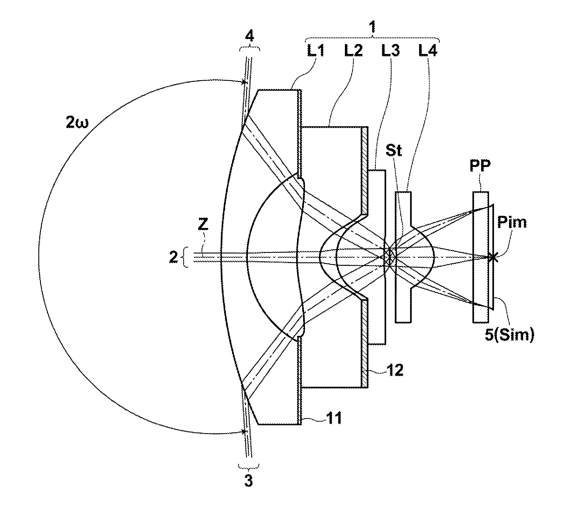
first embodiment
[0139]Further, the imaging lens according to the present invention satisfies the following conditional formula (4):
1.0<D2 / f<2.5 (4),
where
[0140]f: a focal length of an entire system, and
[0141]D2: a distance on an optical axis between first lens L1 and second lens L2.
[0142]When the upper limit of conditional formula (4) is satisfied, it is possible to reduce the size of the lens system. If the value is lower than the lower limit of conditional formula (4), a distance between first lens L1 and second lens L2 becomes short, and the surface shape of the object-side surface of second lens L2 is restricted. Therefore, correction of curvature of field and distortion becomes difficult.
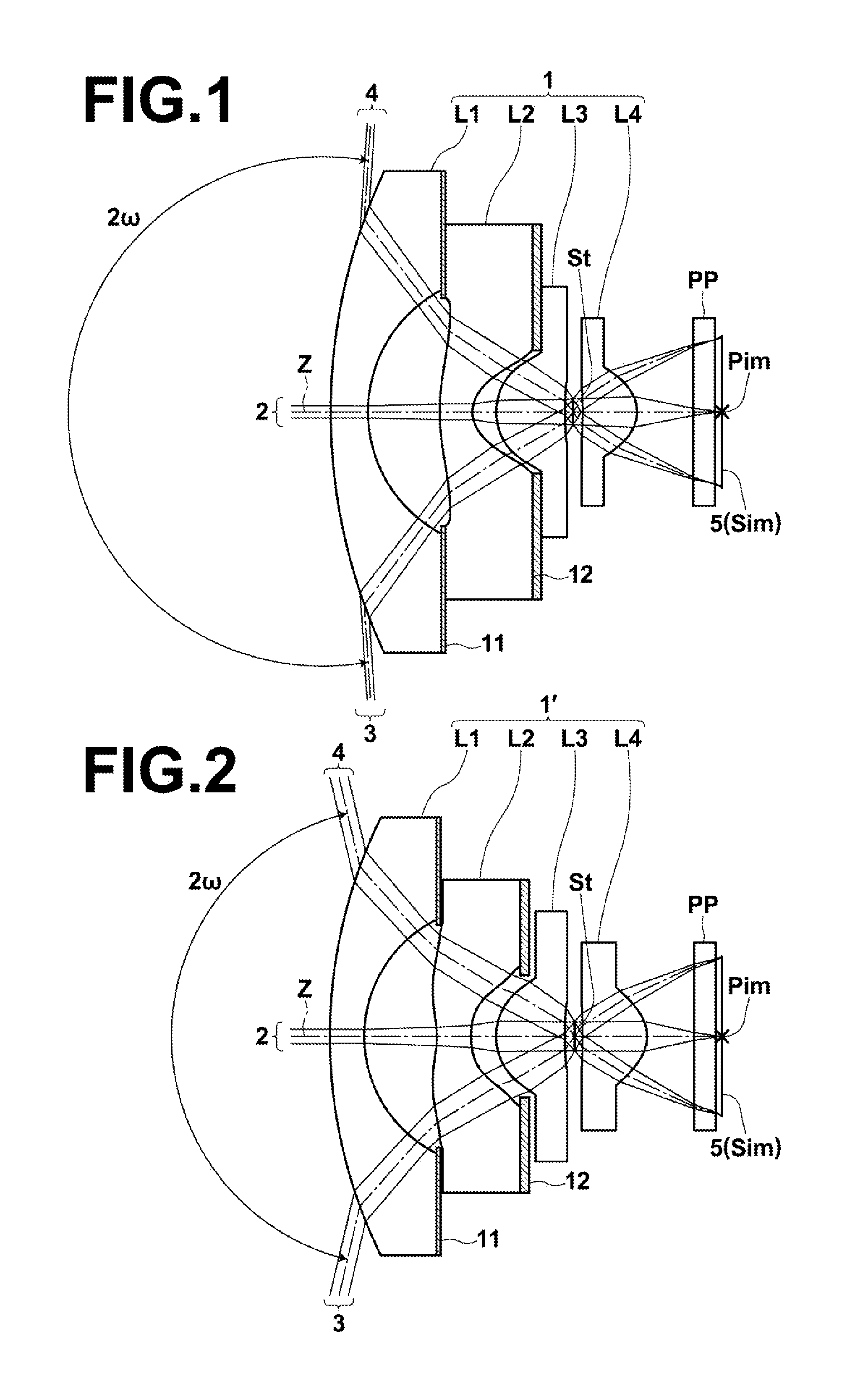
[0143]Next, the structure of a second embodiment of the present invention will be described. An imaging lens according to the second embodiment of the present invention includes negative first lens L1, negative second lens L2 of a biconcave shape, third lens L3 of a plano-convex shape having a convex sur...
second embodiment
[0148]Further, the imaging lens according to the present invention satisfies the following conditional formula (4-1):
1.0<D2 / f<2.8 (4-1),
where
[0149]f: a focal length of an entire system, and
[0150]D2: a distance on an optical axis between first lens L1 and second lens L2.
[0151]When second lens L2 has a biconcave shape, it is possible to easily locate points at an effective diameter edge on the object-side surface of second lens L2 further to the object side, compared with a case in which second lens L2 has a meniscus shape having a convex surface directed toward the object side. Therefore, even if the upper limit is 2.8, it is possible to easily correct curvature of field while preventing the size of the lens system from becoming large. If the value is lower than the lower limit of conditional formula (4-1), a distance between first lens L1 and second lens L2 becomes short, and the surface shape of the object-side surface of second lens L2 is restricted. Therefore, correction o...
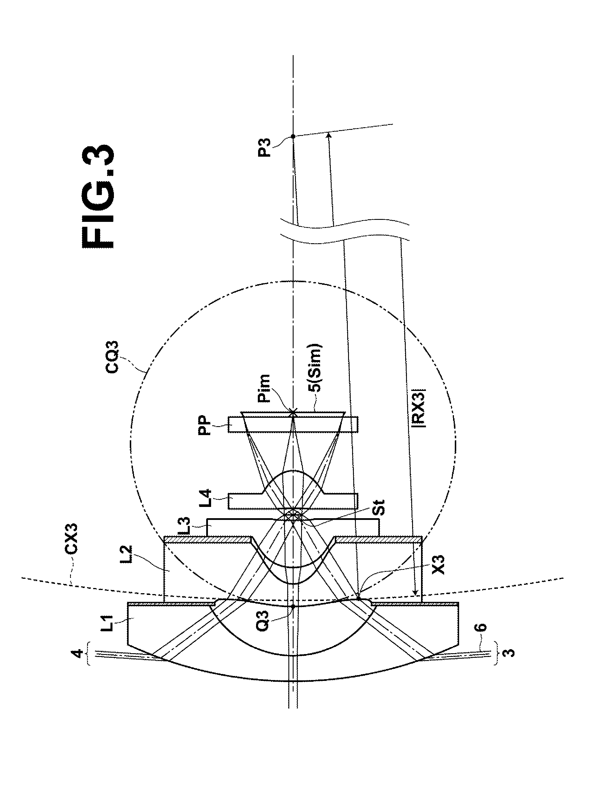
third embodiment
[0156]Further, the imaging lens according to the present invention satisfies the following conditional formula (5):
1.5<f3 / f<3.0 (5),
where
[0157]f: a focal length of an entire system, and
[0158]f3: a focal length of third lens L3.
[0159]When the upper limit of conditional formula (5) is satisfied, it is possible to prevent the power of third lens L3 from becoming too weak, and to easily correct curvature of field and a lateral chromatic aberration. If the value is lower than the lower limit of conditional formula (5), the power of third lens L3 becomes too strong, and a back focus becomes too short, or the power of third lens L3 becomes too strong and an allowable amount of production error of eccentricity becomes too small. Therefore, production becomes difficult.
[0160]Next, the structure of a fourth embodiment of the present invention will be described. An imaging lens according to the fourth embodiment of the present invention includes negative first lens L1, negative second l...
PUM
 Abstract
Description
Claims
Application Information