Evaporation fuel processing device

Active Publication Date: 2014-03-06
AISAN IND CO LTD
View PDF8 Cites 5 Cited by
  • Summary
  • Abstract
  • Description
  • Claims
  • Application Information

AI Technical Summary

Benefits of technology

The present invention aims to provide an evaporation fuel processing device that reduces the amount of residual fuel components in the activated carbon after purging, thereby reducing blow-by of the fuel components from the device to the atmosphere. The invention achieves this by designing the adsorbent layer and separating parts with smaller volume closer to the atmospheric air port and larger volume farther from the port. This results in increased recovery of gas temperature during purging and higher gas temperature inside the device compared to conventional canisters, improving desorption performance and reducing blow-by.

Problems solved by technology

Accordingly, the desorption performance in these adsorbent layers 113 and 112 is degraded, which may result in insufficient desorption of the fuel components.
As a result, a residual amount of the fuel components in the activated carbon after purging becomes large, which may cause blow-by to the atmosphere.

Method used


Image

  • Evaporation fuel processing device
  • Evaporation fuel processing device
  • Evaporation fuel processing device

Examples


embodiment 1

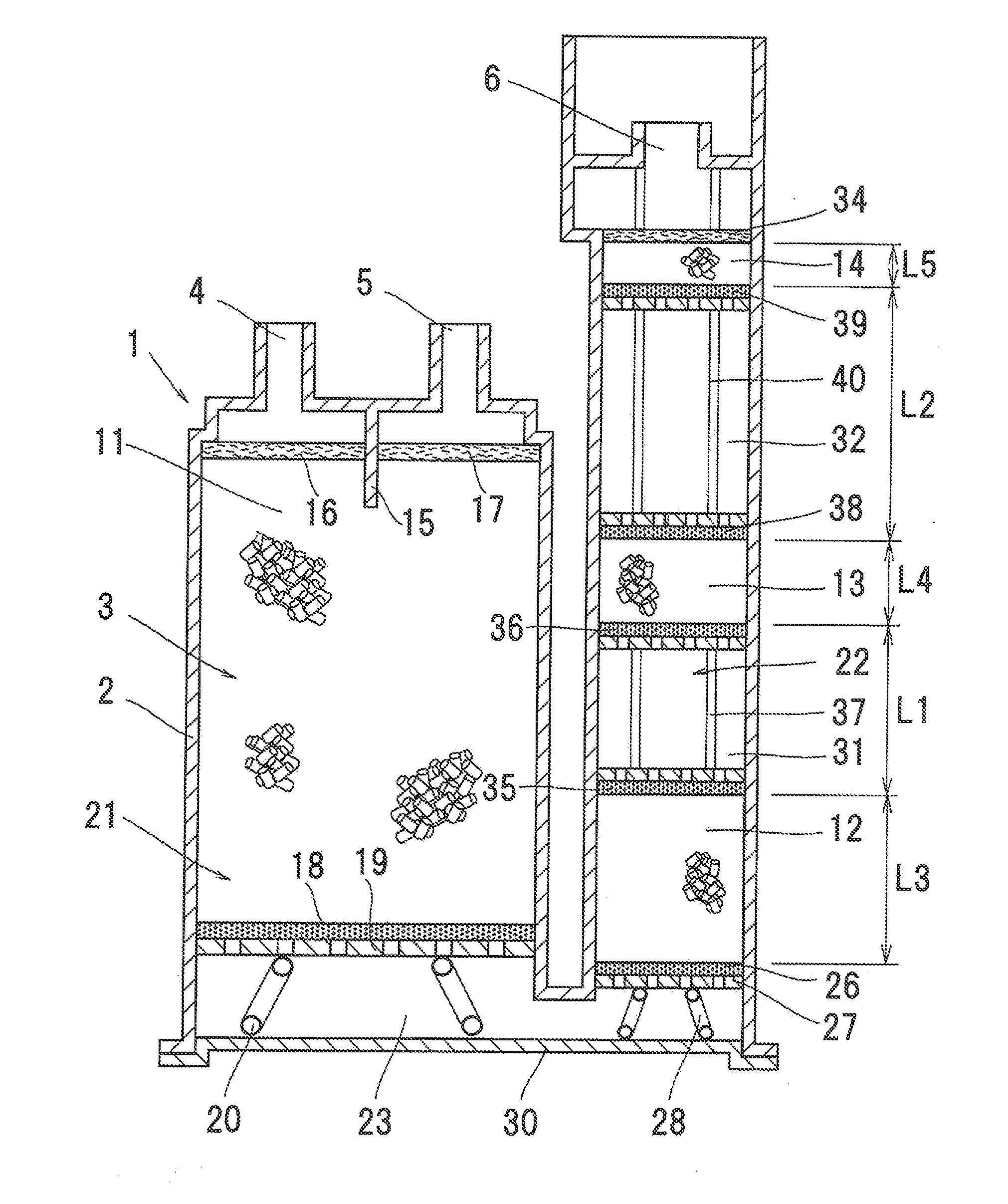
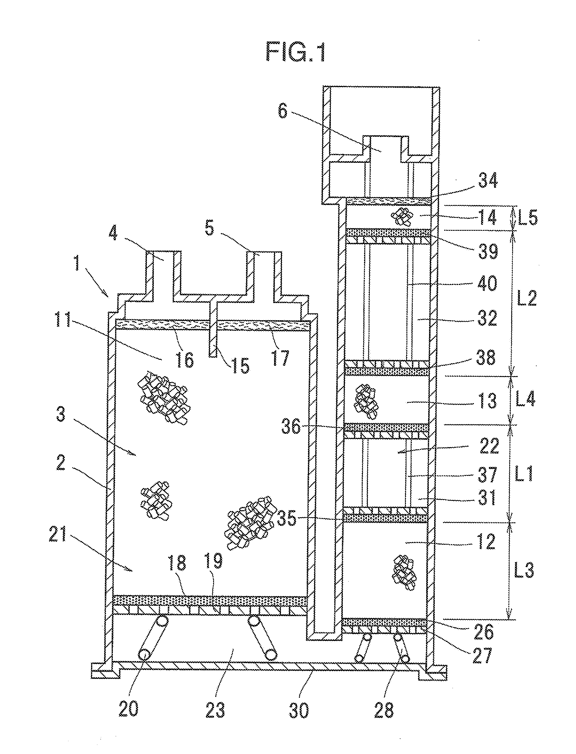
[0025]FIG. 1 shows Embodiment 1 of the present invention.

[0026]As shown in FIG. 1, an evaporation fuel processing device 1 of the present invention includes: a case 2; and a passage 3 formed inside the case 2 so as to allow a fluid to flow therethrough; a tank port 4 and a purge port 5 formed in an end part on one end side of the passage 3 in the case 2; and an atmospheric air port 6 formed in the end part on the other end side.

[0027]Four adsorbent layers: a first adsorbent layer 11, a second adsorbent layer 12, a third adsorbent layer 13, and a fourth adsorbent layer 14, each filled with adsorbent which can adsorb evaporation fuel components are serially disposed in the passage 3. In the present embodiment, activated carbon is used as the adsorbent.

[0028]As shown in FIG. 1, a main chamber 21 communicating with the tank port 4 and the purge port 5, and an auxiliary chamber 22 communicating with the atmospheric air port 6 are formed in the case 2. The main chamber 21 and the auxiliar...

embodiment 2

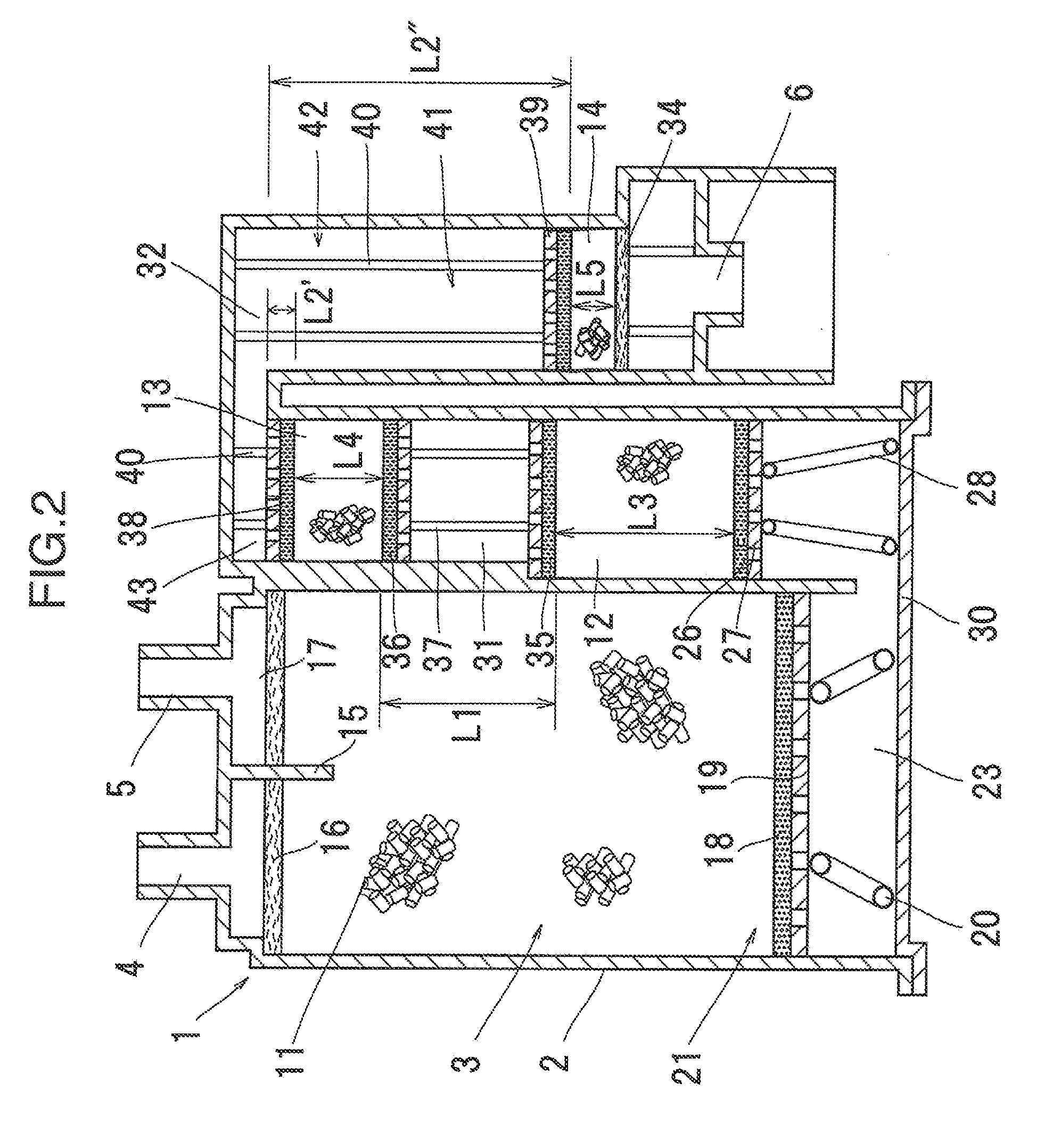
[0065]While in Embodiment 1, the U-shaped passage 3 which is folded back once in the space 23 is formed in the case 2, for example, a passage 41 formed in an N-shape which is folded back twice may be provided in the case 2 as shown in FIG. 2.

[0066]The structure of the main chamber 21 in Embodiment 2 is the same as that of the main chamber 21 in Embodiment 1. In Embodiment 2, an auxiliary chamber 42 corresponding to the region in Claim 1 is formed in a U-shape which is folded back in a space 43. One end of the auxiliary chamber 42 communicates with the space 23, and the other end is provided with the atmospheric air port 6.

[0067]The second adsorbent layer 12 and the third adsorbent layer 13 similar to those in Embodiment 1 are provided between the spaces 23 and 43 in the auxiliary chamber 42, and the first separating part 31 is formed between the second adsorbent layer 12 and the third adsorbent layer 13. In addition, the fourth adsorbent layer 14 similar to the fourth adsorbent laye...

embodiment 3

[0075]A shape of a passage in Embodiment 3 is different from that of the passages 3 and 41 of Embodiments 1 and 2, and for example, a passage 51 formed in a W-shape which is folded back three times may be provided in the case 2 as shown in FIG. 3.

[0076]The structure of the main chamber 21 in Embodiment 3 is the same as that of the main chamber 21 in Embodiment 1. An auxiliary chamber 52 in Embodiment 3 corresponding to the region in Claim 1 is formed in an N-shape which is folded back twice in spaces 53 and 54. One end of the auxiliary chamber 52 communicates with the space 23, and the other end is provided with the atmospheric air port 6.

[0077]The second adsorbent layer 12 and the third adsorbent layer 13 similar to those in Embodiment 1 are provided between the spaces 23 and 35 in the auxiliary chamber 52, and the first separating part 31 is provided between the second adsorbent layer 12 and the third adsorbent layer 13. In addition, the fourth adsorbent layer 14 similar to the fo...


PUM


Abstract

An evaporation fuel processing device is provide including: a passage; a tank port and a purge port on one end side of the passage; an atmospheric air port on the other end side of the passage; and adsorbent layers filled with adsorbent for evaporation fuel components, provided in the passage; a region provided on an atmospheric air port side of the passage, being constituted of three or more adsorbent layers and separating parts for separating the adjacent adsorbent layers, in which a volume of the adsorbent layer is smaller in the adsorbent layer closer to the atmospheric air port, a volume of the separating part is larger closer to the atmospheric air port, and the volume of the separating part located farthest on a tank port side is larger than that of the adsorbent layer located farthest on the atmospheric air port side.

Description

BACKGROUND OF THE INVENTION[0001](1) Field of the Invention[0002]The present invention relates to an evaporation fuel processing device.[0003](2) Description of Related Art[0004]Conventionally, in order to prevent evaporation fuel from being discharged to the atmosphere from a fuel tank and the like of a vehicle, an evaporation fuel processing device (hereinafter also referred to as a canister) which temporarily adsorbs fuel components in the evaporation fuel has been used.[0005]As such a canister, a canister 101 as shown in FIG. 6 is known (e.g., refer to JP-A-2002-235610), which includes: a case 105 formed with a tank port 102, a purge port 103, and an atmospheric air port 104; a main chamber 106 communicating with the tank port 102 and the purge port 103, and an auxiliary chamber 107 communicating with the atmospheric air port 104, the main chamber 106 and the auxiliary chamber 107 formed in the case 105 and communicating with each other in a part on an opposite side of the atmos...

Claims


Application Information

Patent Timeline
IPC IPC(8): F02M25/08
CPCF02M25/0854
Inventor AKIYAMA, TAKANORIKIMOTO, JUNYATAKAMATSU, HIROSHIKOSUGI, RYUJI
Owner AISAN IND CO LTD
Why Eureka
Try Eureka